
Annulus pressure control system for subsea wells

a technology of pressure control system and subsea well, which is applied in the direction of water installation, sealing/packing, and borehole/well accessories, etc., can solve the problem of lengthening the time required to run the heavier casing, and achieve the effect of avoiding clogging of small lines, minimizing the thermal effect of warm fluid, and saving material and installation costs

Inactive Publication Date: 2006-05-23
BAKER HUGHES INC
View PDF11 Cites 20 Cited by
  • Summary
  • Abstract
  • Description
  • Claims
  • Application Information

AI Technical Summary

Benefits of technology

[0004]The annulus pressure is controlled by displacing incompressible fluid with compressible fluid in the annulus. The displaced fluid is filtered to avoid clogging small lines. The presence of compressible fluid minimizes the thermal effect of warm fluid in the production tubing on annulus pressure. As a result, thinner wall casing can be used, for considerable savings in material and installation cost.

Problems solved by technology

The need to contain the pressures encountered due to this heating effect causes additional expense for heavier walled casing and generally lengthens the time required to run the heavier casing into the well.

Method used


Image

  • Annulus pressure control system for subsea wells
  • Annulus pressure control system for subsea wells
  • Annulus pressure control system for subsea wells

Examples


Embodiment Construction

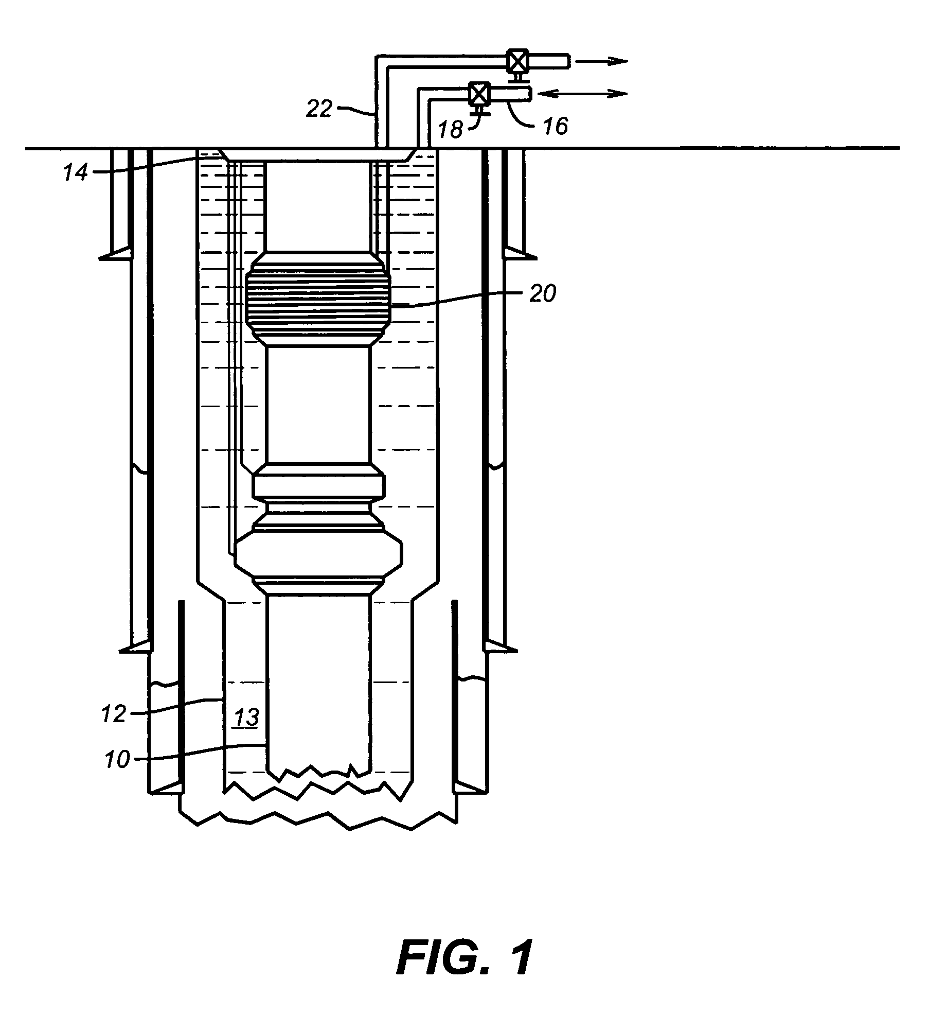
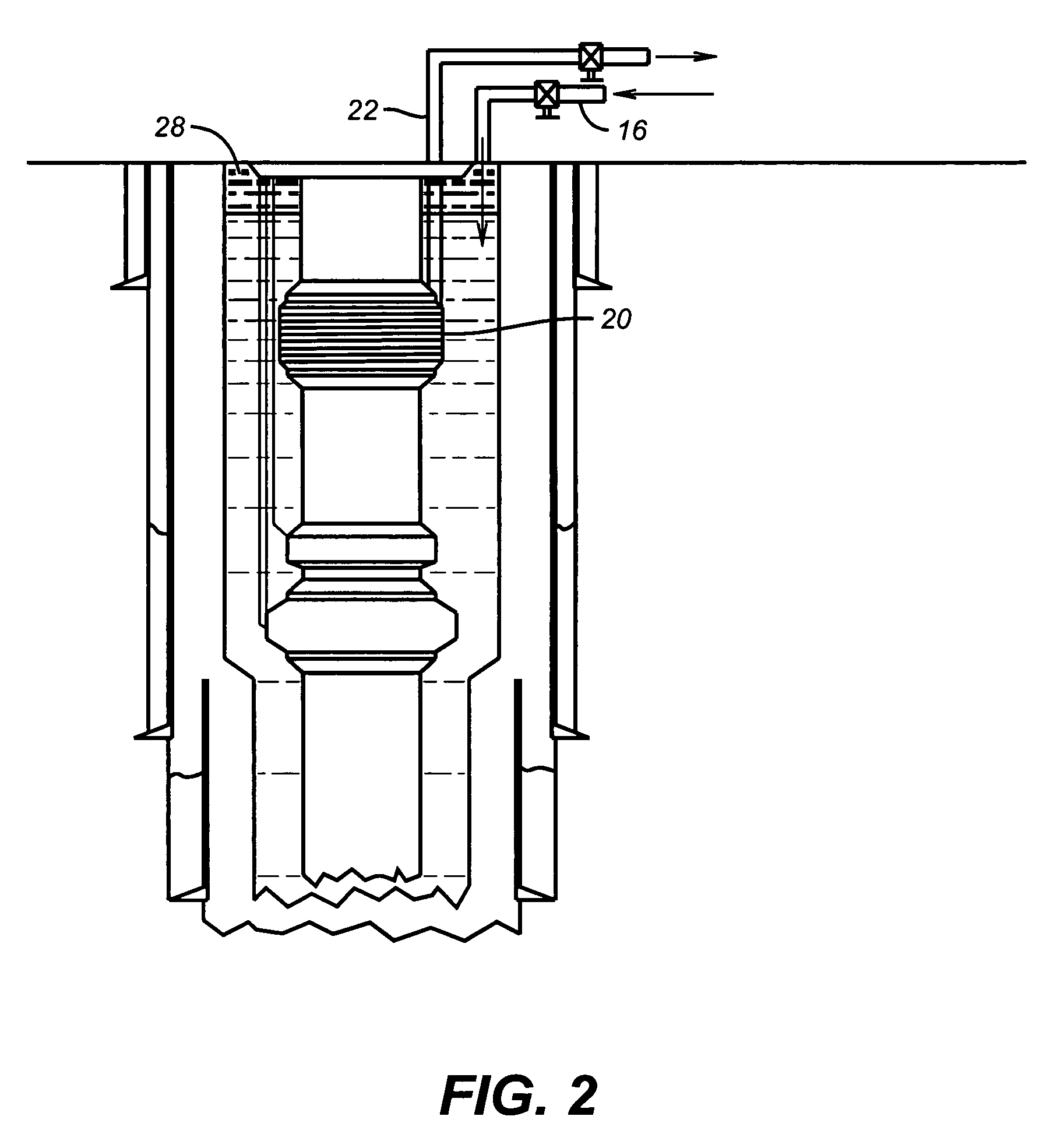
[0009]FIG. 1 shows production tubing 10 surrounded by casing 12 defining the A annulus 13 in between. Hanger 14 supports casing 12 in a known manner. The Christmas tree is omitted but it is a known design that also supports the hanger 14. Access into the annulus 13 is through line 16 by operating valve 18. A pressurized gas source, not shown, can be connected to line 16 and valve 18 opened to allow displacement of incompressible fluid in annulus 13 through screen 20 and through line 22 and valve 24 to a proper location for disposition. Since line 22 is normally a small diameter, normally ½ or ¾ inches in diameter, screen 20 insures that line 22 does not plug with solids during the displacement procedure, shown in FIG. 2.

[0010]FIG. 2 illustrates the application of gas pressure into line 16 represented by arrow 26. As a result, a pocket of compressible fluid 28, preferably nitrogen, has formed near the top of annulus 13. At the same time, some compressible fluid has been displaced thr...


PUM


Abstract

The annulus pressure is controlled by displacing incompressible fluid with compressible fluid in the annulus. The displaced fluid is filtered to avoid clogging small lines. The presence of compressible fluid minimizes the thermal effect of warm fluid in the production tubing on annulus pressure. As a result, thinner wall casing can be used, for considerable savings in material and installation cost.

Description

FIELD OF THE INVENTION[0001]The field of this invention is a pressure control system particularly useful in controlling annulus pressure in subsea wells.BACKGROUND OF THE INVENTION[0002]In subsea applications, the various casing strings are hung on a hanger in a concentric manner and in descending size order. The annular space between casing runs and the central production tubing is referred to as the A annulus. When production begins, thermal effects act on the fluid in the A annulus to raise its pressure. This occurs because by the nature of how subsea completions take place, the A annulus is full of seawater or / and well fluids, all of which are incompressible. When the production tubing heats up during production, the fluid in the A annulus is expanded. As a result, the casing has had to be sized to contain this pressure increase caused by warming an A annulus full of incompressible fluid. The need to contain the pressures encountered due to this heating effect causes additional ...

Claims


Application Information

Patent Timeline
Patent Type & Authority Patents(United States)
IPC IPC(8): E21B29/12E21B33/068E21B33/076E21B41/00E21B43/00E21B43/08
CPCE21B33/068E21B33/076E21B43/088E21B41/00E21B43/00E21B33/13
Inventor ADAMS, JEFFREY K.STRATTAN, SCOTT C.
Owner BAKER HUGHES INC
Learn More