Eureka AIR delivers breakthrough ideas for toughest innovation challenges, trusted by R&D personnel around the world.

Microfluidic viscometer

a microfluidic and viscometer technology, applied in the field of analytical tools, can solve the problems of affecting and the application of electrical fields can have detrimental effects in some instances, and achieve the effect of improving the accuracy and repeatability of microfluidic flows

Inactive Publication Date: 2006-05-09
CAPLIPER LIFE SCI INC
View PDF30 Cites 114 Cited by
  • Summary
  • Abstract
  • Description
  • Claims
  • Application Information

AI Technical Summary

Benefits of technology

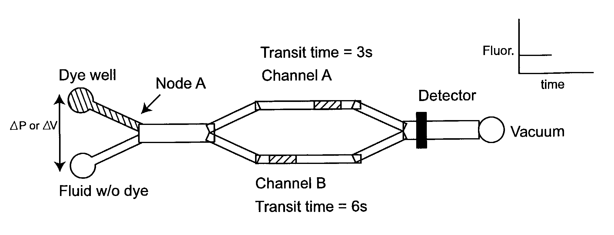
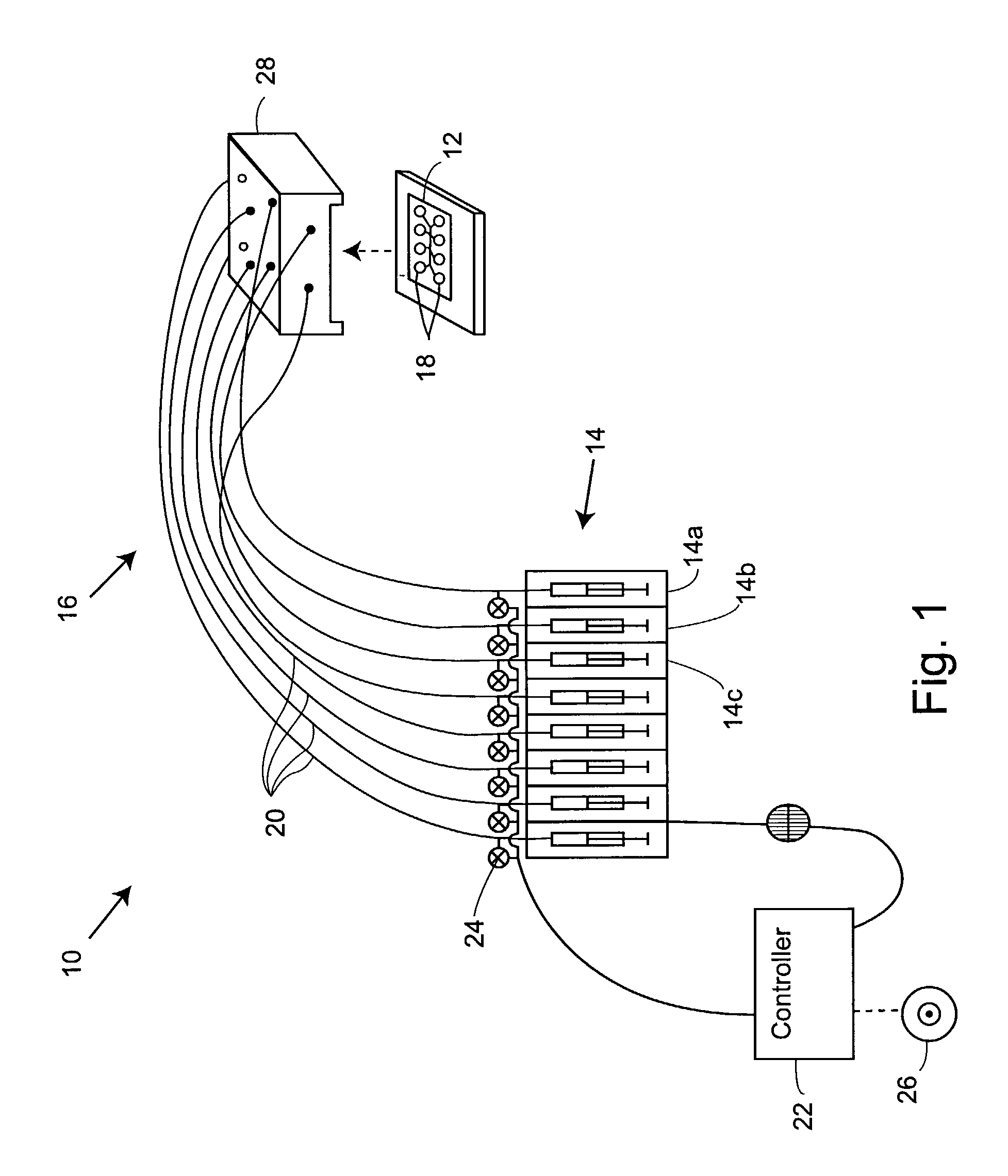
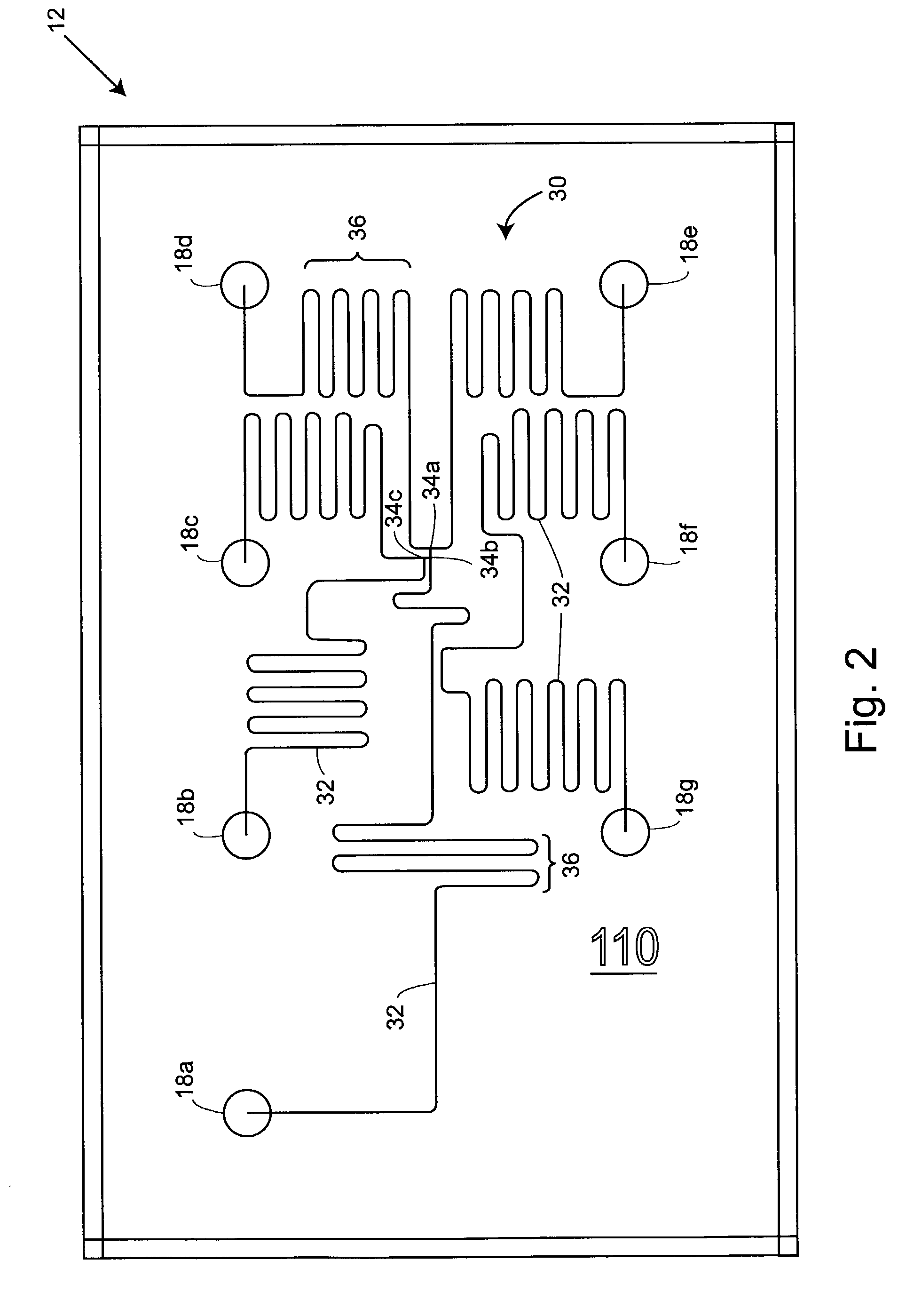
[0013]In many embodiments, a body having channel walls defines the network. The network can include a plurality of channels with one or more intersections therebetween. A flow generator (e.g., a pressure or voltage source) coupled to the network can induce a flow of the sample fluid within the first segment. A first intersection can be in communication with the first segment, with the sensor coupled to the network at a sensor location disposed downstream of the first segment. This allows the sensor to sense a change in the flow which propagates from the first intersection to the sensor location so as to determine the viscosity of the sample fluid.

Problems solved by technology

For example, while electrokinetic material transport systems provide many benefits in the micro-scale movement, mixing, and aliquoting of fluids, the application of electrical fields can have detrimental effects in some instances.
Regardless of the mechanism used to effect movement of fluid and other materials within a microfluidic channel network, accuracy and repeatability of microfluidic flows can be problematic.

Method used


Image

  • Microfluidic viscometer
  • Microfluidic viscometer
  • Microfluidic viscometer

Examples


Embodiment Construction

[0073]The present invention will provide improved microfluidic devices, systems, and methods. The systems of the present invention will often determine a viscosity (or other characteristics) of a sample fluid by making use of the resistance to flow present within the small channels of a microfluidic network. Viscosities can be determined without, for example, adding fluorescent dyes or other detectable substances in a manner which could alter or distort the indicated viscosity. Toward that end, the fluid sample can flow through a flow resisting channel while sample fluid is substantially free of a substance which is detectable to the sensor.

[0074]As used herein, a sample is “substantially free” of a detectable substance if an associated viscosity sensor does not receive a sufficient signal from the detectable substance so as to identify the presence or speed of the detectable substance. It should be noted that such detectable substances can be, and often are, added to the sample flu...


PUM

PropertyMeasurementUnit
volumesaaaaaaaaaa
volumesaaaaaaaaaa
flow ratesaaaaaaaaaa

Abstract

Microfluidic devices, systems, and methods measure viscosity, flow times, and / or pressures, other flow characteristics within the channels, and the measured flow characteristics can be used to generate a desired flow. Multi-reservoir pressure modulator and pressure controller systems, electrokinetic systems and / or other fluid transport mechanisms can generate the flow, controllably mix fluids, and the like.

Description

CROSS-REFERENCES TO RELATED APPLICATIONS[0001]This application is a continuation-in-part of U.S. application Ser. No. 10 / 008,604, filed Nov. 9, 2001, now U.S. Pat. No. 6,681,616, issued Jan. 27, 2004, which is a continuation-in-part of U.S. application Ser. No. 09 / 792,435 filed on Feb. 23, 2001 now U.S. Pat. No. 6,915,679. This application claims priority to and benefit of these prior applications. This application also claims the benefit of and priority to U.S. Provisional Patent Application No. 60 / 216,793 filed on Jul. 7, 2000, and U.S. Provisional Patent Application No. 60 / 184,390 filed Feb. 23, 2000. The full disclosures of each of these prior applications are incorporated herein by reference.BACKGROUND OF THE INVENTION[0002]The present invention is generally related to analytical tools for the biological and chemical sciences, and in a particular embodiment, provides microfluidic devices, systems, and methods for determining the viscosity of fluids within microfluidic channels ...

Claims


Application Information

Patent Timeline
Patent Type & Authority Patents(United States)
IPC IPC(8): G01N11/04G01F1/708B01L3/00B01L9/00G01N11/08G01N27/447G01N35/10G05D7/06
CPCB01L3/5027G05D7/0694B01L9/527G01N27/44791B01L3/502715B01L3/50273B01L3/502746B01L2200/027B01L2300/0663B01L2300/0816B01L2300/0861B01L2300/0864B01L2300/0867B01L2400/0406B01L2400/0415B01L2400/0487B01L2400/084G01N11/08G01N2035/1044
Inventor SPAID, MICHAELCHOW, ANDREA W.WANG, BENJAMIN N.CHIEN, RING-LINGPARCE, J. WALLACEKOPF-SILL, ANNE R.MOLHO, JOSHTRIPATHI, ANUBHAVKERBY, MATTHEW B.
Owner CAPLIPER LIFE SCI INC
Why Eureka
Eureka Blog
Learn More