Method and system for checking track integrity

a technology of integrity and track, applied in the field of railways, can solve problems such as track occupation, rail breakage, and inability to detect voltage,

Inactive Publication Date: 2006-05-02
SIEMENS MOBILITY INC
View PDF53 Cites 86 Cited by
  • Summary
  • Abstract
  • Description
  • Claims
  • Application Information

AI Technical Summary

Problems solved by technology

Alternatively, if there is a break in one of the rails between the point at which the voltage is applied and the point at which the voltage measuring device is located, the voltage won't be detected.
Thus, if the voltage cannot be detected, there is either a break in the rail or the track is occupied by another train.
In either event, it is not safe for a train to enter the section of track monitored by the track circuit.
There are two major problems with such systems.
First, the operation of the track circuit in the absence of an oncoming train wasted power.
This limited the use of such systems to locations near a source of power.
Because human beings are not perfect, signals were sometimes missed and accidents resulted.
While this solution does conserve power and allow the broken rail detection circuit to be used with a solar cell or battery power source, it has the disadvantage of high maintenance costs associated with the “feed”.
This system is inefficient in that it places an increased processing load on the dispatcher, as the dispatcher is forced to receive and send such messages each time each train reaches a new track circuit.
It is also problematic when communications between the dispatcher and the broken rail detection circuit become interrupted.
However, in the systems known to the inventors, the track integrity circuit remains on even when the signal lights are out (the main reason the signal lights are turned off is to make the signal lights less attractive to vandals).
Furthermore, the track integrity circuits in these systems conserve relatively large amounts of power.
These systems are therefore not suitable for use with solar and / or battery power.

Method used


Image

  • Method and system for checking track integrity
  • Method and system for checking track integrity
  • Method and system for checking track integrity

Examples


Embodiment Construction

[0018]The present invention will be discussed with reference to preferred embodiments of train control systems. Specific details, such as specific track circuits and signals, are set forth in order to provide a thorough understanding of the present invention. The preferred embodiments discussed herein should not be understood to limit the invention. Furthermore, for ease of understanding, certain method steps are delineated as separate steps; however, these steps should not be construed as necessarily distinct nor order dependent in their performance.

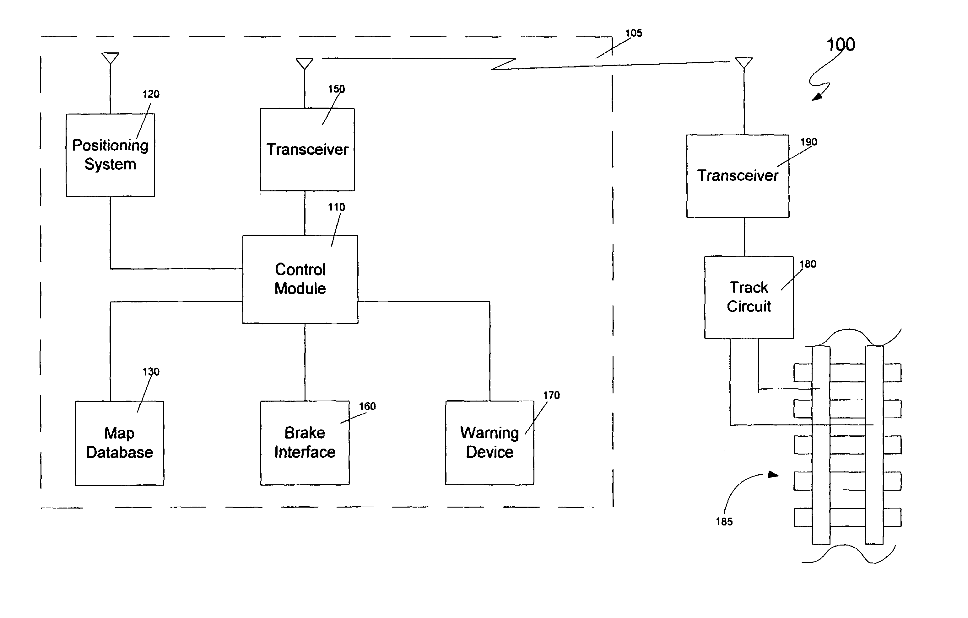
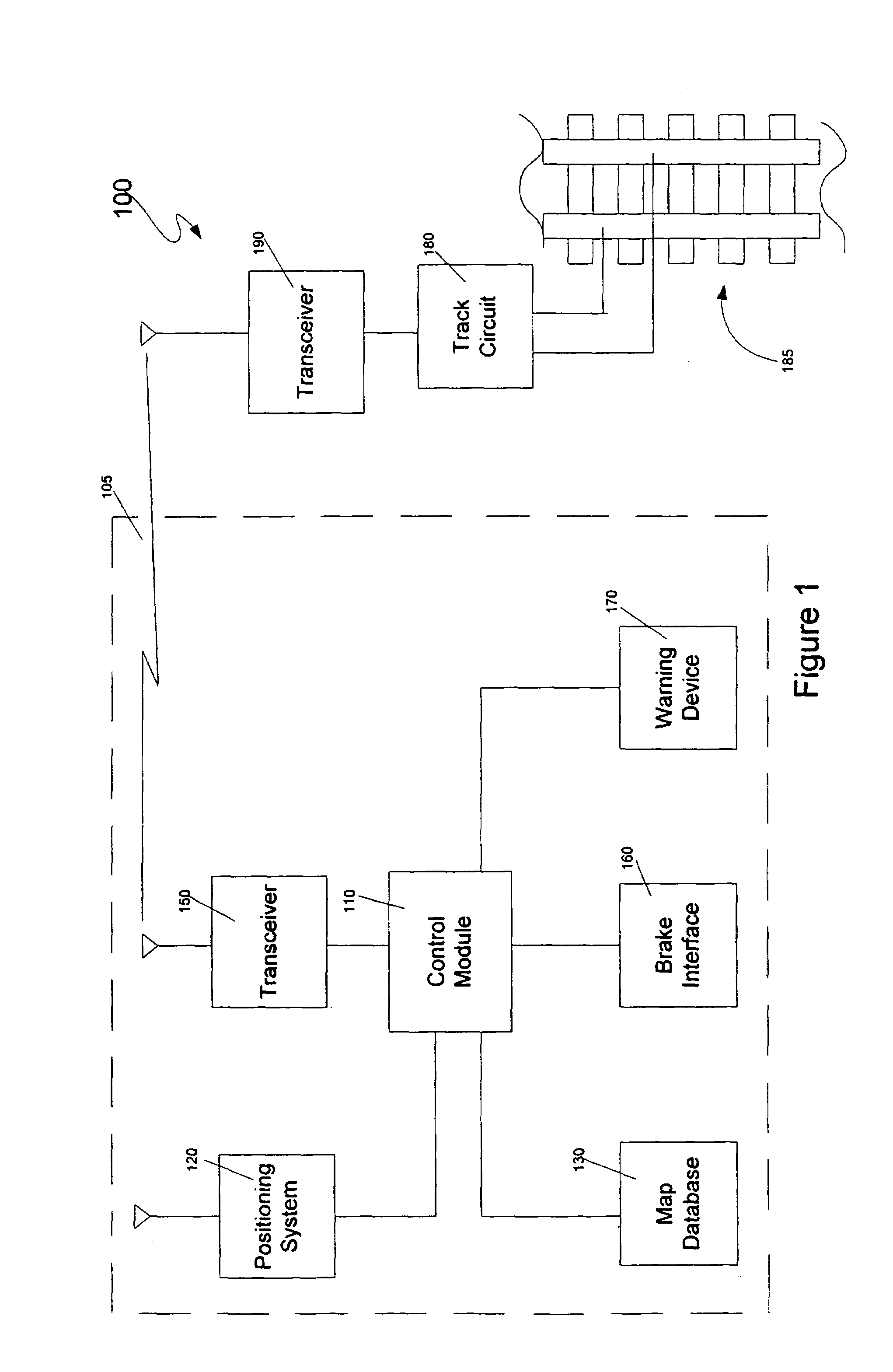
[0019]Referring now to the drawings, wherein like reference numerals designate identical or corresponding parts throughout the several views, FIG. 1 is a logical block diagram of a train control system 100 according to an embodiment of the present invention. The train control system includes a train unit 105 and a plurality of pairs of track circuits 180 and transceivers 190 that monitor various sections of track 185. These track circui...


PUM


Abstract

A train control system includes a control module that determines a position of a train using a positioning system and consults a database to determine when the train is approaching a portion of track monitored by a track circuit. When the train is near a track circuit, but while the train is still far enough away from the track circuit such that the train can be stopped before reaching the portion of track monitored by the track circuit, the train transmits an interrogation message to a transceiver associated with the track circuit. When the track circuit receives the interrogation message, a test is initiated. The test results are transmitted back to the train. The train takes corrective action if the track circuit fails to respond or indicates a problem.

Description

[0001]This application is a continuation of application Ser. No. 10 / 267,962 filed on Oct. 10, 2002, now U.S. Pat. No. 6,845,953.BACKGROUND OF THE INVENTION[0002]1. Field of the Invention[0003]The invention relates to railroads generally, and more particularly to a method and system for identifying problems with train tracks.[0004]2. Discussion of the Background[0005]Track circuits of various types have been used for many years in the railroad industry to determine whether sections or blocks of train track are safe for transit. These track circuits determine such things as whether there is a train in a section of track, whether there is a broken rail in a section of track, whether there has been an avalanche or whether snow or other debris is on the section of track, and whether the section of track is properly aligned with a bridge (with moveable and / or permanent spans). These and other such track circuits will be referred to herein as “track integrity circuits” or simply “track cir...

Claims


Application Information

Patent Timeline
Patent Type & Authority Patents(United States)
IPC IPC(8): B61L3/00B61L23/04
CPCB61L3/125B61L23/047B61L23/041B61L2205/04
Inventor KANE, MARK EDWARDSHOCKLEY, JAMES FRANCISHICKENLOOPER, HARRISON THOMAS
Owner SIEMENS MOBILITY INC
Why Eureka
Try Eureka