Eureka AIR delivers breakthrough ideas for toughest innovation challenges, trusted by R&D personnel around the world.

Method and system for determining relative positions of networked mobile communication devices

a mobile communication device and relative position technology, applied in the field of determining relative positions of objects, can solve the problems of not being able to assist fallen comrades, police officers, firefighters, etc., and not being able to maintain accurate and updated knowledge of one another's locations

Active Publication Date: 2006-04-18
DRS SIGNAL SOLUTIONS
View PDF21 Cites 171 Cited by
  • Summary
  • Abstract
  • Description
  • Claims
  • Application Information

AI Technical Summary

Problems solved by technology

While operating in such areas, the individuals often find it difficult or impossible to maintain accurate and updated knowledge of one another's locations because the structures in an urban area block visual contact between the individuals.
As a result of the inability to establish visual contact, soldiers in urban environments often become casualties of friendly fire.
Similarly, police officers, firefighters and soldiers are not able to assist fallen comrades who may be nearby, yet cannot be visually observed.
Current electronic position location systems do not provide a satisfactory solution to the problem of providing an individual, who is part of a group of individuals, with current information as to the positions of other individuals in the group when the individuals of the group are located in an urban environment where visual contact among and between individuals of the group is difficult or not possible.
For example, a global positioning satellite (“GPS”) navigational system typically performs poorly inside of a building or in an urban canyon.
Similarly, a position determination system for locating cellular phones, such as developed in accordance with the FCC's E911 initiative, is usually inadequate because the positioning information generated is of insufficient accuracy, is limited to a description of location only in two dimensions and depends upon a sophisticated, fixed infrastructure that is not always available in the areas in which many groups will need to conduct operations.

Method used


Image

  • Method and system for determining relative positions of networked mobile communication devices
  • Method and system for determining relative positions of networked mobile communication devices
  • Method and system for determining relative positions of networked mobile communication devices

Examples


Embodiment Construction

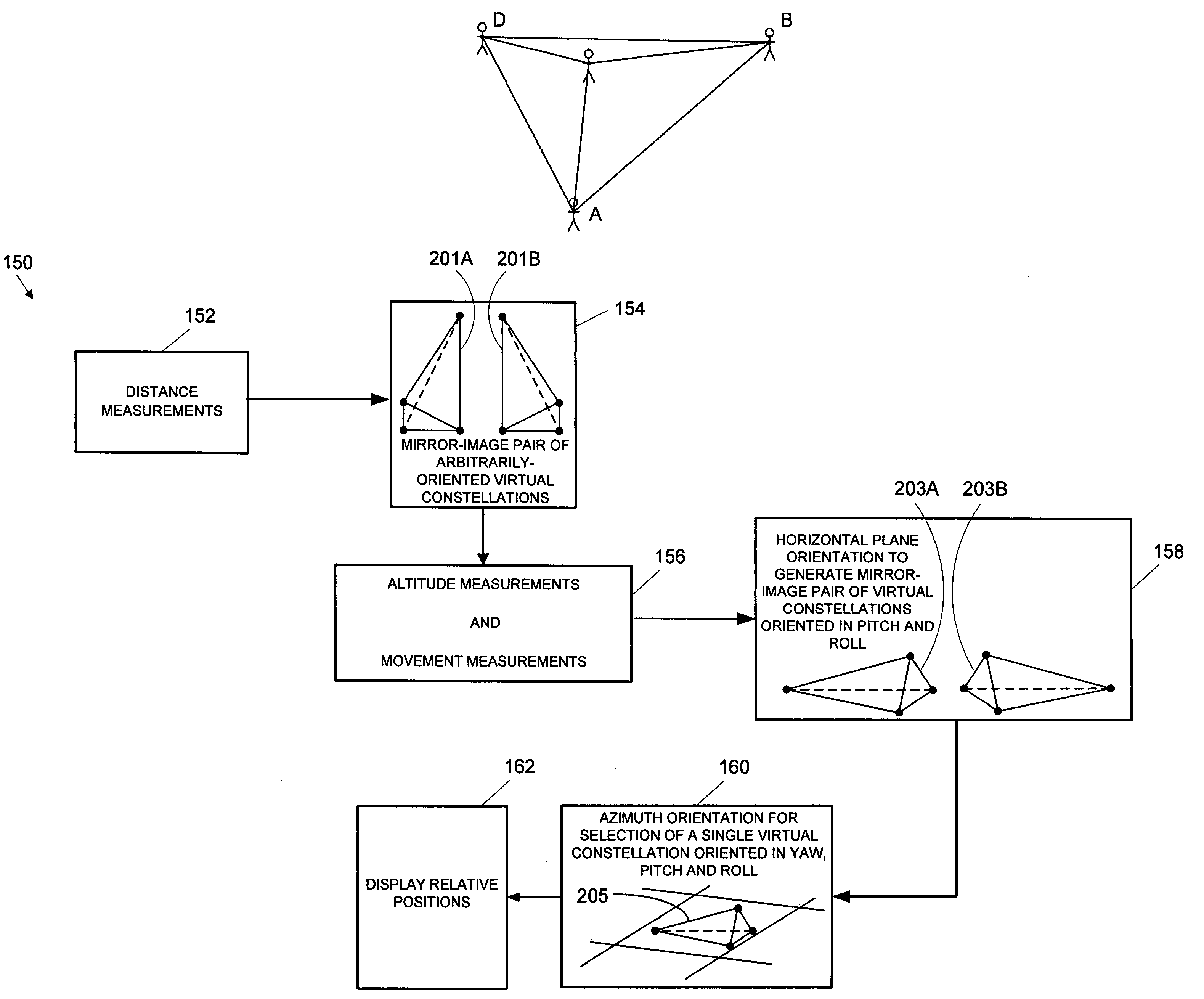
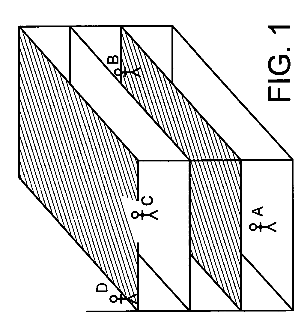
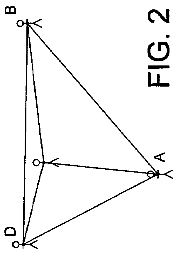
[0020]In accordance with the present invention, relative positions of individuals in a group, where each individual carries a mobile communications device for wirelessly communicating with each of the other individuals to form a group of networked mobiles, are determined at each of the mobiles without the use of external positioning information, such as GPS information, which oftentimes is unavailable at various locations where the group may be operating. FIG. 1 illustrates how a group of individuals A, B, C and D, such as police officers, firefighters, guards or soldiers, may be dispersed to locations in and around a multistory building, which is a typical environment in which GPS-based or like external electronic signal positioning systems may perform poorly or fail completely. If the position of each individual is represented as a point, the formation of the group can be viewed as a constellation of points in space as shown in FIG. 2. At any instant in time, the locations of the ...


PUM


Abstract

Relative positions of a plurality of mobiles communication devices, which form a wirelessly networked group of mobiles, are determined at each of the mobiles of the group without the need for external positioning information obtained from a location remote from the actual locations of the mobiles of the group. The relative positions are determined at the mobiles of the group based on mobile-to-mobile range measurements, distance and direction of movement measurements and altitude measurements made at the respective mobiles.

Description

CROSS REFERENCE TO RELATED APPLICATION[0001]This application claims the benefit of U.S. Provisional Application No. 60 / 402,964 filed Aug. 13, 2002, assigned to the assignee of this application and incorporated by reference herein.FIELD OF THE INVENTION[0002]The present invention relates generally to determining relative positions of objects and, more particularly, determining relative positions of a plurality of wirelessly networked mobile communications devices without using remotely generated positioning information.BACKGROUND OF THE INVENTION[0003]Groups of individuals, such as police officers, firefighters, rescue workers or soldiers, often need to conduct operations in built up urban areas. While operating in such areas, the individuals often find it difficult or impossible to maintain accurate and updated knowledge of one another's locations because the structures in an urban area block visual contact between the individuals. As a result of the inability to establish visual co...

Claims


Application Information

Patent Timeline
IPC IPC(8): H04Q7/20G01S5/02G01S11/02G01S19/09G01S19/46H04B7/26H04W64/00
CPCG01S5/0289H04W64/00G01S11/02
Inventor RORABAUGH, C. BRITTON
Owner DRS SIGNAL SOLUTIONS
Why Eureka
Eureka Blog
Learn More