
Axle assembly with transverse mounted electric motors

a technology of electric motors and axles, applied in the direction of electric propulsion mounting, transportation and packaging, gearing, etc., can solve the problems of a large number of electric motors, difficult to package relatively large electric motors in a multi-axle vehicle configuration, and not being the most effective for the operation requirements of such vehicles

Inactive Publication Date: 2006-04-18
ARVINMERITOR TECH
View PDF30 Cites 64 Cited by
  • Summary
  • Abstract
  • Description
  • Claims
  • Application Information

AI Technical Summary

Benefits of technology

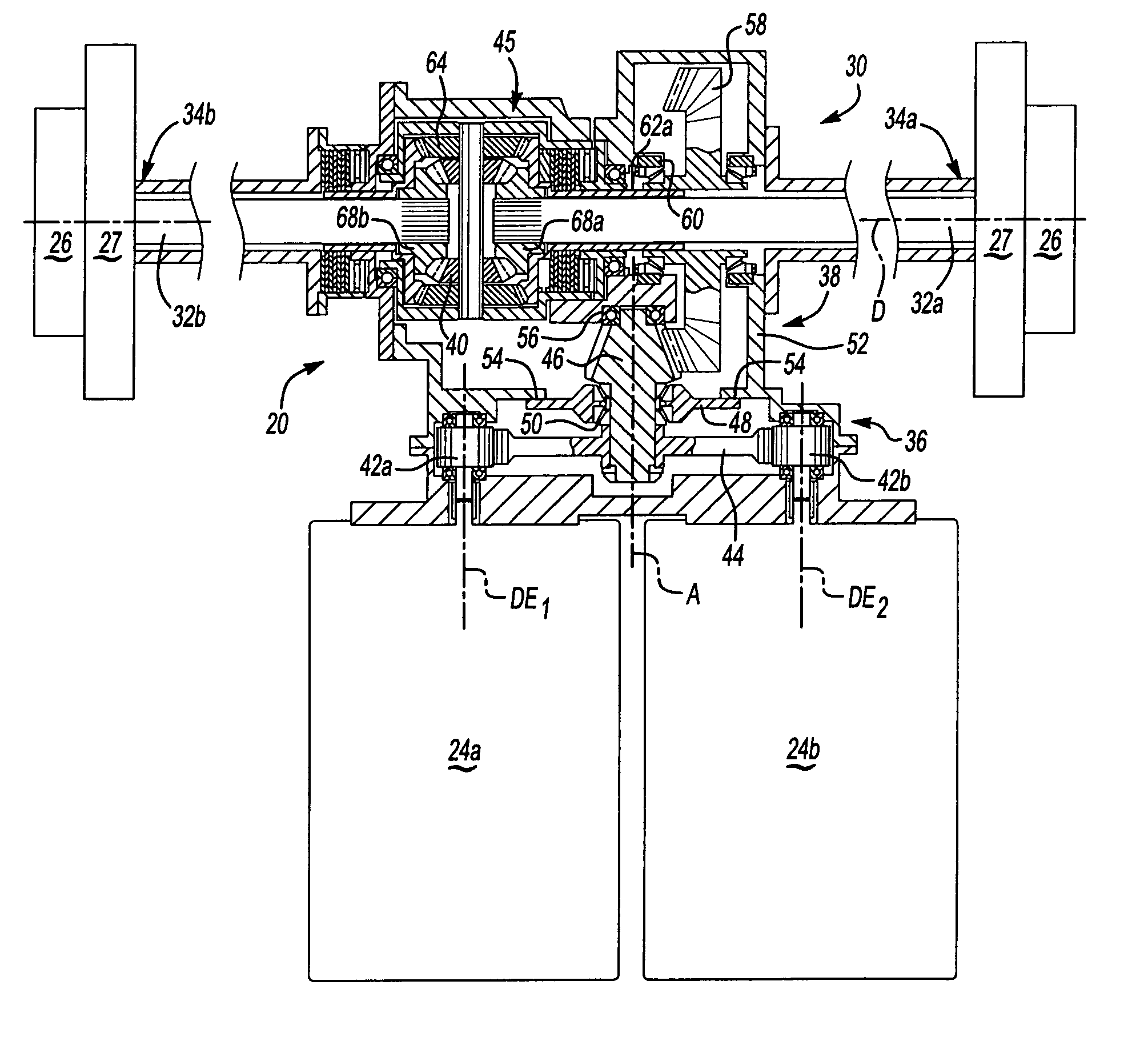
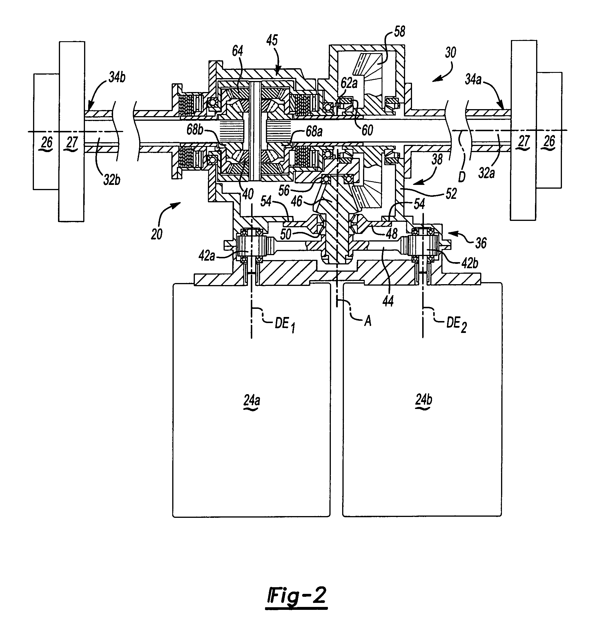
The present invention is an axle assembly that includes two electric motors that drive a gearbox assembly. This gearbox assembly then drives the vehicle's wheels through two axle shafts. The electric motors are located along axes that are transverse to the first axis. This design allows for a compact and lightweight axle assembly that can benefit from the use of smaller electric motors. The invention also provides a versatile axle assembly that can be used in different vehicle configurations with minimal modification. Overall, the invention provides a lightweight and compact electric motor-driven axle configuration that can be used in multi-axle military and specialty vehicles.

Problems solved by technology

The electric motors are typically sized to meet both torque and speed requirements which may not be the most effective for the operational requirements of such vehicles.
Relatively large electric motors are often utilized to meet the torque requirements which may result in an oversized motor for most operational conditions.
Moreover, the relatively large electric motors may be difficult to package in a multi-axle vehicle configuration.

Method used


Image

  • Axle assembly with transverse mounted electric motors
  • Axle assembly with transverse mounted electric motors
  • Axle assembly with transverse mounted electric motors

Examples


Embodiment Construction

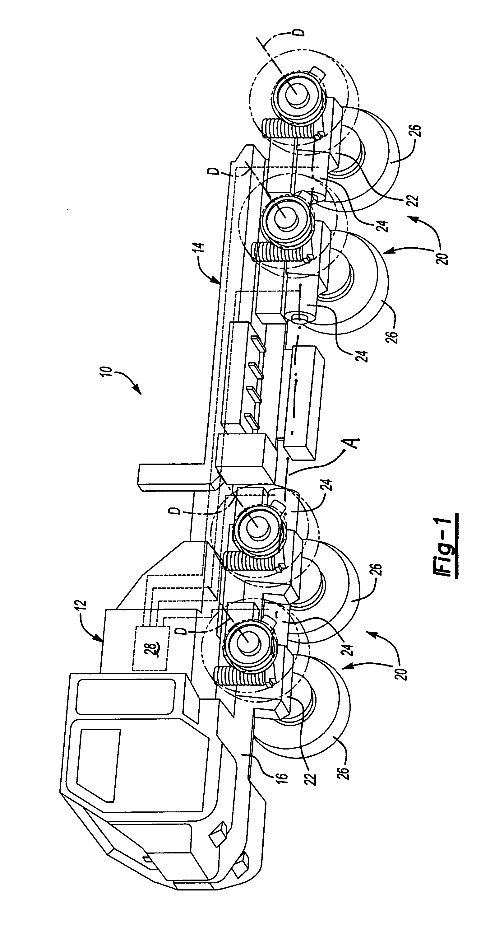
[0014]FIG. 1 illustrates a schematic partial phantom view of a multi-axle vehicle 10 having a body 12 supported upon a frame 14. The frame 14 preferably includes a pair of main longitudinal members 16. It should be understood that although a particular vehicle arrangement is disclosed in the illustrated embodiment, other vehicles will benefit from the present invention.

[0015]A multiple of axle assemblies 20 each includes an axle 22 driven by one or more electric motors 24. Each axle assembly 20 defines an axis of rotation D substantially transverse the longitudinal members 16 to drive one or more wheel assemblies 26 supported by a suspension assembly 27 (illustrated schematically). The electric motors 24 are driven by a prime mover 28 which is preferably a hybrid electric drive which powers each of the axle assemblies 20 by powering the electric motors 24. It should be understood, however, that other prime movers such as diesel engines, gas turbines among others will also benefit fr...


PUM


Abstract

An axle assembly includes a first and a second electric motor which drive a gearbox assembly substantially therebetween. The electric motors drive the gearbox assembly which drives the vehicle wheels through a first and second axle shaft located along a first axis. The electric motors are located along axes which are substantially transverse to the first axis. The electric motors drive the gearbox assembly which includes a first stage gear reduction, a second stage gear reduction and a third stage gear reduction. A relatively lightweight and compact axle assembly is thereby provided which will benefit from an electric motor of reduced size.

Description

BACKGROUND OF THE INVENTION[0001]The present invention relates to an axle assembly which utilizes a plurality of electric motors, and more particularly to an axle configuration which locates the electric motors in a transverse arrangement to the axle.[0002]There is an increasing demand for the use of hybrid electric driven and hybrid electric assisted vehicles. Hybrid electric vehicles typically utilize electric motor driven axles which are often of a multi-axle configuration in military and specialty vehicle systems.[0003]The electric motors are typically sized to meet both torque and speed requirements which may not be the most effective for the operational requirements of such vehicles. Relatively large electric motors are often utilized to meet the torque requirements which may result in an oversized motor for most operational conditions. Moreover, the relatively large electric motors may be difficult to package in a multi-axle vehicle configuration.[0004]Accordingly, it is desi...

Claims


Application Information

Patent Timeline
Patent Type & Authority Patents(United States)
IPC IPC(8): F16H37/06B60K1/00B60B35/12B60B37/00B60K1/02B60K6/36B60K6/48B60K6/52B60K7/00B60K17/356
CPCB60K6/48B60K6/52B60K17/356B60K6/36B60K1/02Y10T74/19014B60K2001/001B60W2300/185B60Y2200/14F16H3/50F16H48/08F16H2200/0021F16H2200/0034F16H2200/2005Y02T10/6221Y02T10/6265Y02T10/62
Inventor BENNETT, JOHN L.
Owner ARVINMERITOR TECH
Learn More