
Method and apparatus for paying bills electronically using machine readable information from an invoice

a bill payment system and machine-readable technology, applied in billing/invoicing, instruments, data processing applications, etc., can solve the problems of loss of the ability to connect a particular consumer with a particular biller without any prior connection, and the consumer cannot decide to pay a new biller and make a payment without the intervening delay

Inactive Publication Date: 2006-04-11
VISA INT SERVICE ASSOC
View PDF18 Cites 53 Cited by
  • Summary
  • Abstract
  • Description
  • Claims
  • Application Information

AI Technical Summary

Benefits of technology

[0011]An improved bill paying system is...

Problems solved by technology

Because paper documents do not change hands, billers must rely on the consumer for data capture of information from the invoice, which is generally less reliable than electronic (e.g., optically scanned) data capture from remittance stubs at the biller's site.
The problem with this approach is that the ability to connect a particular consumer with a particular biller without any prior connection is lost, since the consumer must have had the biller previously verified and placed on the pick list.
Thus, a consumer cannot decide to pay a new biller and make a payment without the intervening delay for verification.
The pick list approach is also undesirable because C-B account numbers can change without any awareness of the consumer.
If pick lists are used, or the consumer relies on other means of prestoring the C-B account number, the transaction will be in error once each five years.
While this system is useful for a single biller and where current bills are paid in full, it does not include a biller identifier and therefore is not useful for a global system.
Furthermore, there is no provision for automatic data capture of the data provided.
A consumer must enter the number as printed on the bill, and entry errors are expected, requiring the consumer to reenter the approval code.

Method used


Image

  • Method and apparatus for paying bills electronically using machine readable information from an invoice
  • Method and apparatus for paying bills electronically using machine readable information from an invoice
  • Method and apparatus for paying bills electronically using machine readable information from an invoice

Examples


Embodiment Construction

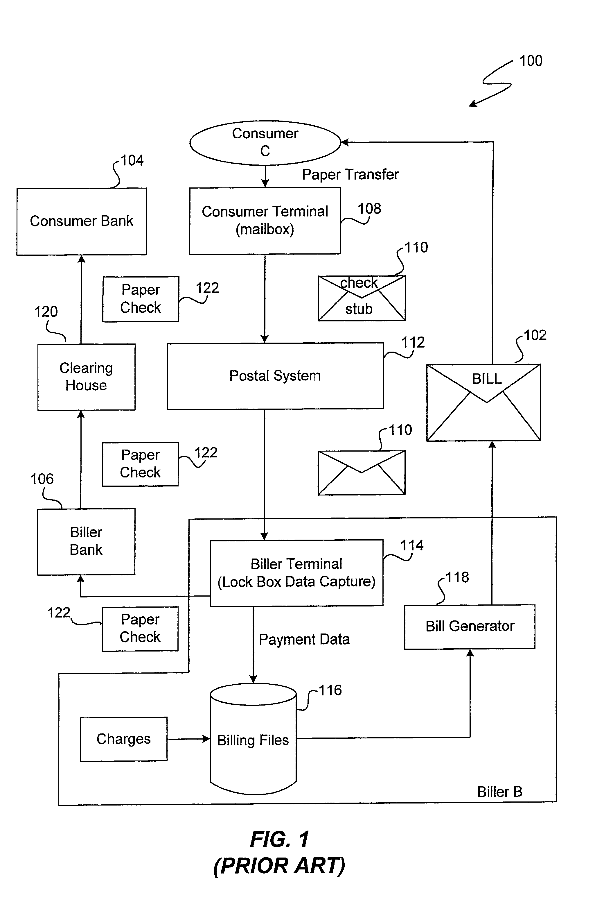
[0023]FIG. 1 shows a bill payment system 100 which is commonly used today to pay bills, where a consumer C pays a bill to a biller B when B sends a bill 102 to C. It should be understood that the term “consumer” is used here as an example of a bill payor, and the invention is not limited to use where the bill payor is a consumer. For example, the invention works equally well where the payor is a reseller. The actual payment of the bill occurs when a consumer bank (C bank) 104 transfers funds from an account maintained for C to a biller bank (B bank) 106, who then credits the funds to an account held for B. The other elements of system 100 are: a consumer terminal 108, which serves as the point of transit for a bill payment 110 into a postal system 112, a biller terminal 114, which is the destination of bill payment 110, a billing database 116 and a bill generator 118.

[0024]The bill payment process begins when biller B generates a bill for consumer C using billing database 116 and bi...


PUM


Abstract

Data capture which occurs at the consumer end of an electronic bill pay transaction is assisted by machine readable information in a standardized format on an invoice where the machine readable information includes biller identification and a C-B account number and the information is readable at the consumer end without prior arrangements being made specifically between the consumer and the biller. The biller identification is either a universal biller reference number or sufficient information to allow manual identification and contact with the biller. The machine readable information is an optically-readable bar code, characters in a font designed for error-free character recognition by optical or magnetic means.

Description

[0001]This application is a continuation of application Ser. No. 08 / 521,623, filed Aug. 31, 1995 now U.S. Pat. No. 6,438,527, which is a continuation-in-part of application Ser. No. 08 / 146,515, filed Nov. 1, 1993, issued as U.S. Pat. No. 5,465,206 on Nov. 7, 1995.BACKGROUND OF THE INVENTION[0002]The present invention relates to the field of electronic bill payment systems (“bill pay”) which allow a consumer to direct their bank, an agent of their bank, or a non-bank bill pay service bureau to pay amounts owed to merchants, service providers and other billers who bill consumers for amounts owed.[0003]U.S. Pat. No. 5,465,206 issued to James J. Hilt et al. teaches a bill pay system in where each participating payee is assigned a biller reference number (“BRN”). That patent (“the Hilt Patent”) is commonly owned by the assignee of the present application and is incorporated by reference herein for all purposes. In the Hilt bill pay system, a consumer could make a payment to a biller with...

Claims


Application Information

Patent Timeline
IPC IPC(8): G06F17/00G06Q20/00G06Q40/00
CPCG06Q20/02G06Q20/023G06Q20/04G06Q20/0425G06Q40/02G06Q20/14G06Q20/425G06Q30/04G06Q20/102
Inventor POWAR, WILLIAM L.
Owner VISA INT SERVICE ASSOC
Learn More