
Method and apparatus for maximizing receiver performance utilizing mid-packet gain changes

a technology of gain change and receiver, applied in the direction of amplitude demodulation, coding, code conversion, etc., can solve the problems of amplifier and mixer to clip or saturate, degrade the performance of the communication system, and achieve the effect of improving the reception of signals

Inactive Publication Date: 2006-04-11
QUALCOMM INC
View PDF10 Cites 51 Cited by
  • Summary
  • Abstract
  • Description
  • Claims
  • Application Information

AI Technical Summary

Benefits of technology

[0016]It is an object of the present invention to provide for improved signal reception using a mid-packet gain change.
[0017]It is another object of the present invention to improve the blocker rejection capability of a receiver.

Problems solved by technology

For example, if the gain is set too low, noise from the various amplifiers and mixers in the receive chain will be significant compared to the size of the desired signal, and will thereby degrade performance.
On the other hand, if the gain is set too high, the desired signal, or undesired signals in nearby frequency channels will cause the amplifiers and mixers to clip or saturate.
The resulting non-linear behavior of these active circuits would degrade the performance of the communication system.
Because the modulation type may change in the middle of a packet (at least after the header), scaling the signal to its optimum level is challenging.
Since the receiver does not know the modulation format, and thus the data rate of the body of the packet, immediately, it cannot know the optimum scaling to use at the beginning of the packet.
While this signal sizing will prove correct if the packet really does contain data modulated in the most complex way, if the packet contains data that is modulated in a less complex way, then that signal sizing will have been larger than necessary, and sacrifice potential ability to withstand interference.
This has at least two disadvantages in a packet-based communication system.
First, the undesired signals may come and go abruptly in a packet-based system, and by the time they are detected, the desired packet may already be ruined.
But changing the gain in the middle of a symbol can cause data to be ruined due to the change in signal magnitude and / or phase.

Method used


Image

  • Method and apparatus for maximizing receiver performance utilizing mid-packet gain changes
  • Method and apparatus for maximizing receiver performance utilizing mid-packet gain changes
  • Method and apparatus for maximizing receiver performance utilizing mid-packet gain changes

Examples


Embodiment Construction

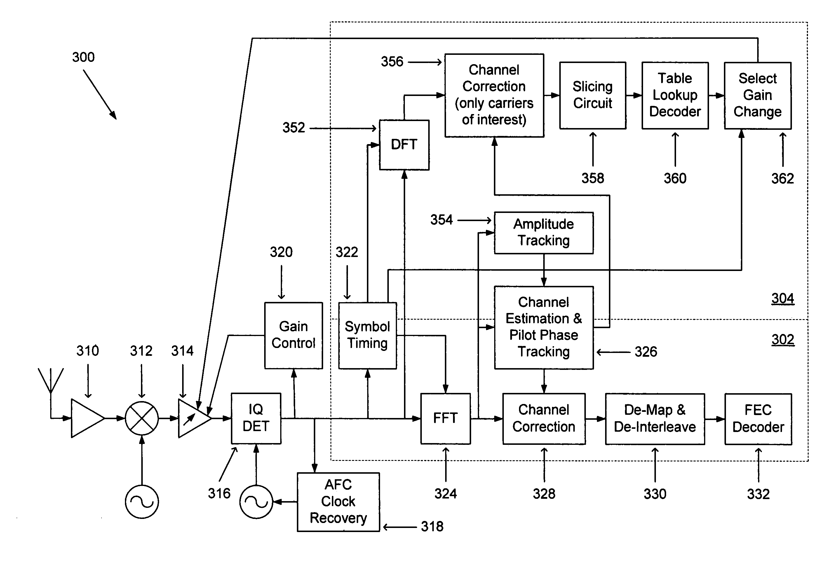
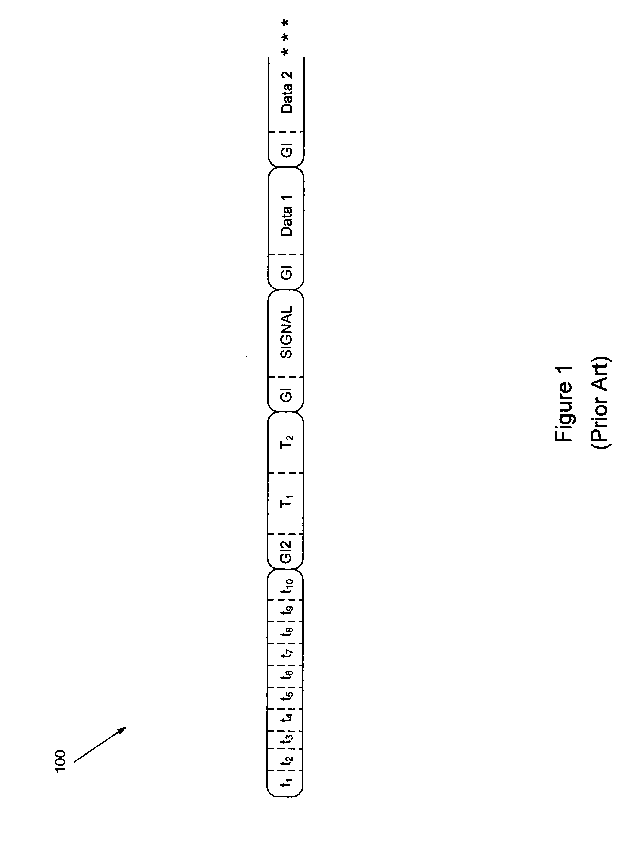
[0030]The present invention, in a preferred embodiment, operates upon an OFDM signal 100 such as described previously with respect to FIG. 1 that operates according to the 802.11(a) standard, and as such the description of the invention provided hereinafter will be made in that context. It is understood, however, that the present invention can operate upon any signals that would benefit from the mid-packet gain adjustment described herein.

[0031]According to the present invention, automatic gain control is further enhanced to improve the blocker rejection capability of the receiver. Since the receiver has no information of the packet data rate during the initial automatic gain control operation that takes place during the short training symbol sequence, as described above, the present invention assumes a certain amount of power back-off due to the blocker power, as explained earlier. As, however, the data rate in a received packet increases, the blocker specification becomes more rel...


PUM


Abstract

The present invention provides a method of and an apparatus for changing the gain of a receive path amplifier during the middle of a packet transmission, and particularly changing the gain during a guard interval between a symbol with encoding bits disposed therein and a subsequent data symbol encoded in a manner corresponding to the encoding bits.

Description

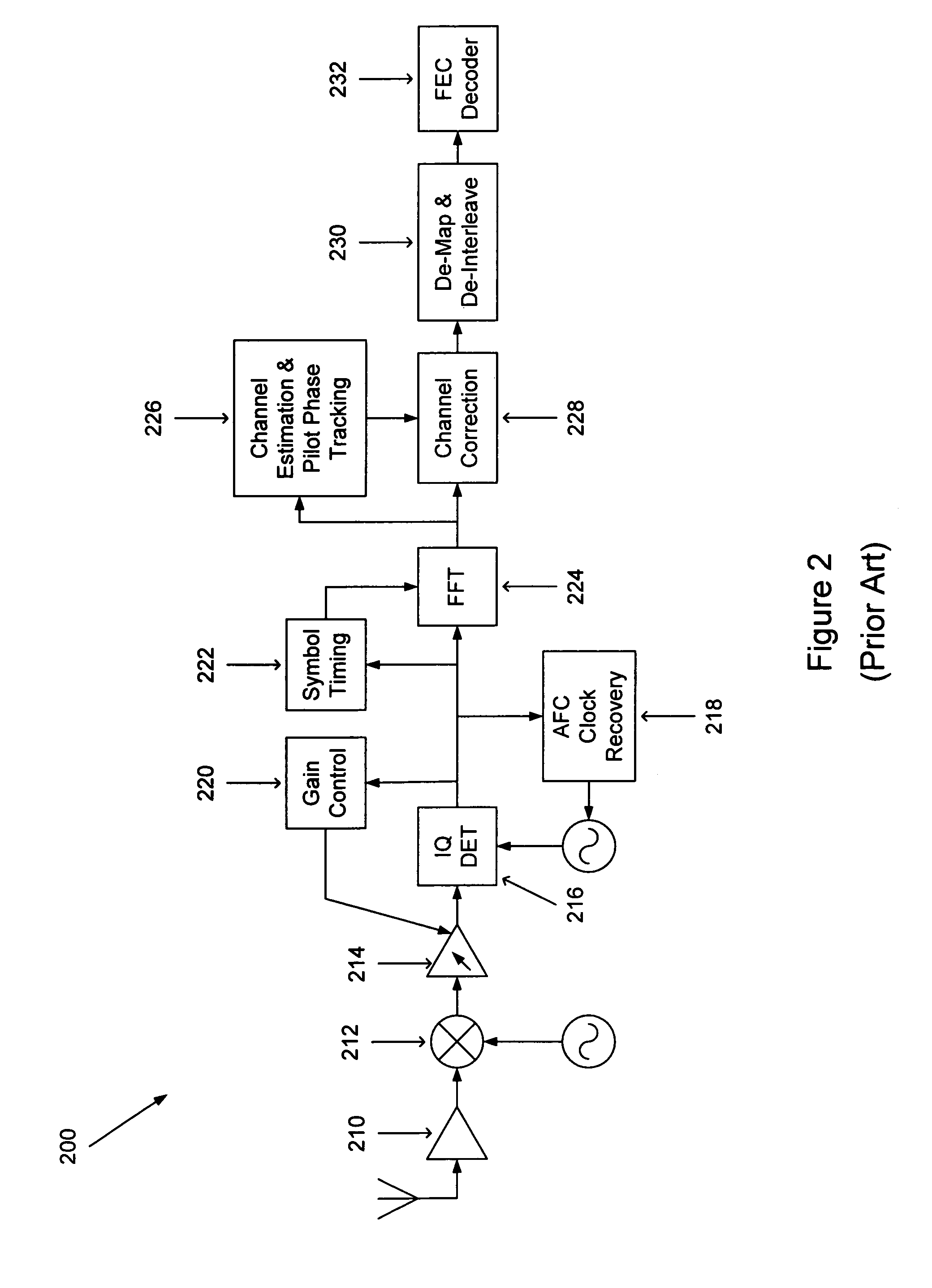
FIELD OF THE INVENTION[0001]The present invention relates to a method of and apparatus for mid-packet changing of the gain of a receive path amplifier.BACKGROUND OF THE RELATED ART[0002]In a communication system, transceivers are electronic devices that include receivers that receive incoming signals and transmitters that transmit outgoing signals, and are very well known.[0003]Certain types of digital receivers have the ability to receive incoming signals that are transmitted with different modulation schemes, also known as multi-rate modulation schemes. Thus, a single receiver can, at different times, receive signals that have been modulated in, for instance, a binary phase shift key (BPSK) modulation format or a quadrature amplitude modulation (QAM) format. Generally, it is advantageous to use a more complex modulation scheme if possible, since more information can be communicated for a given bandwidth using a modulation scheme that is more complex. But which modulation scheme to...

Claims


Application Information

Patent Timeline
IPC IPC(8): H04L27/06H03G3/30H04L1/00H04L27/26
CPCH03G3/3052H04L27/2647H04L1/0054H04L27/2605
Inventor MCFARLAND, WILLIAMMENG, TERESA H.HUSTED, PAUL J.THOMSON, JOHN S.
Owner QUALCOMM INC
Learn More