Magnetron, and microwave oven and high-frequency heating apparatus each equipped with the same

a high-frequency heating and microwave oven technology, applied in the field of magnets and microwave ovens, can solve the problems of increasing the weight and manufacturing cost of magnetron, increasing the length of parts, and increasing the weight of magnetron, and achieve the effect of low cos

Inactive Publication Date: 2006-04-11
SAMSUNG ELECTRONICS CO LTD
View PDF7 Cites 7 Cited by
  • Summary
  • Abstract
  • Description
  • Claims
  • Application Information

AI Technical Summary

Benefits of technology

[0010]Accordingly, it is an aspect of the present invention to provide a magnetron that is capable of being miniaturized and manufactured at a low cost due to the miniaturization.
[0011]Another aspect of the present invention is to provide a magnetron that is capable of reducing the demagnetization of permanent magnets by suppressing the heating of the permanent magnets, thus increasing the oscillation efficiency of the magnetron.

Problems solved by technology

In the meantime, in the conventional magnetron, the permanent magnets are provided above and below the anode in consideration of the uniformity and symmetry of magnetic flux across the activating space of the magnetron, so the height and volume of the magnetron and the lengths of parts (such as the center lead, the side lead, the antenna, the upper and lower shield cups and ceramic (not shown)) made of expensive materials are increased, thus increasing the weight and manufacturing cost of the magnetron.
Hence, the demagnetization of the permanent magnets is caused by the heating of the permanent magnets, and the size of the magnetron is increased in consideration of the decrease of the oscillation efficiency, thus reducing the oscillation efficiency of the magnetron and increasing the weight and manufacturing cost of the magnetron, respectively.

Method used


Image

  • Magnetron, and microwave oven and high-frequency heating apparatus each equipped with the same
  • Magnetron, and microwave oven and high-frequency heating apparatus each equipped with the same
  • Magnetron, and microwave oven and high-frequency heating apparatus each equipped with the same

Examples


Embodiment Construction

[0045]Reference will now be made in detail to the present preferred embodiments of the present invention, examples of which are illustrated in the accompanying drawings, wherein like reference numerals refer to the like elements throughout. The embodiments are described below in order to explain the present invention by referring to the figures. Additionally, for clarity of description, the rotational direction of magnetic flux due to the polarization of north and south poles of a magnet is ignored.

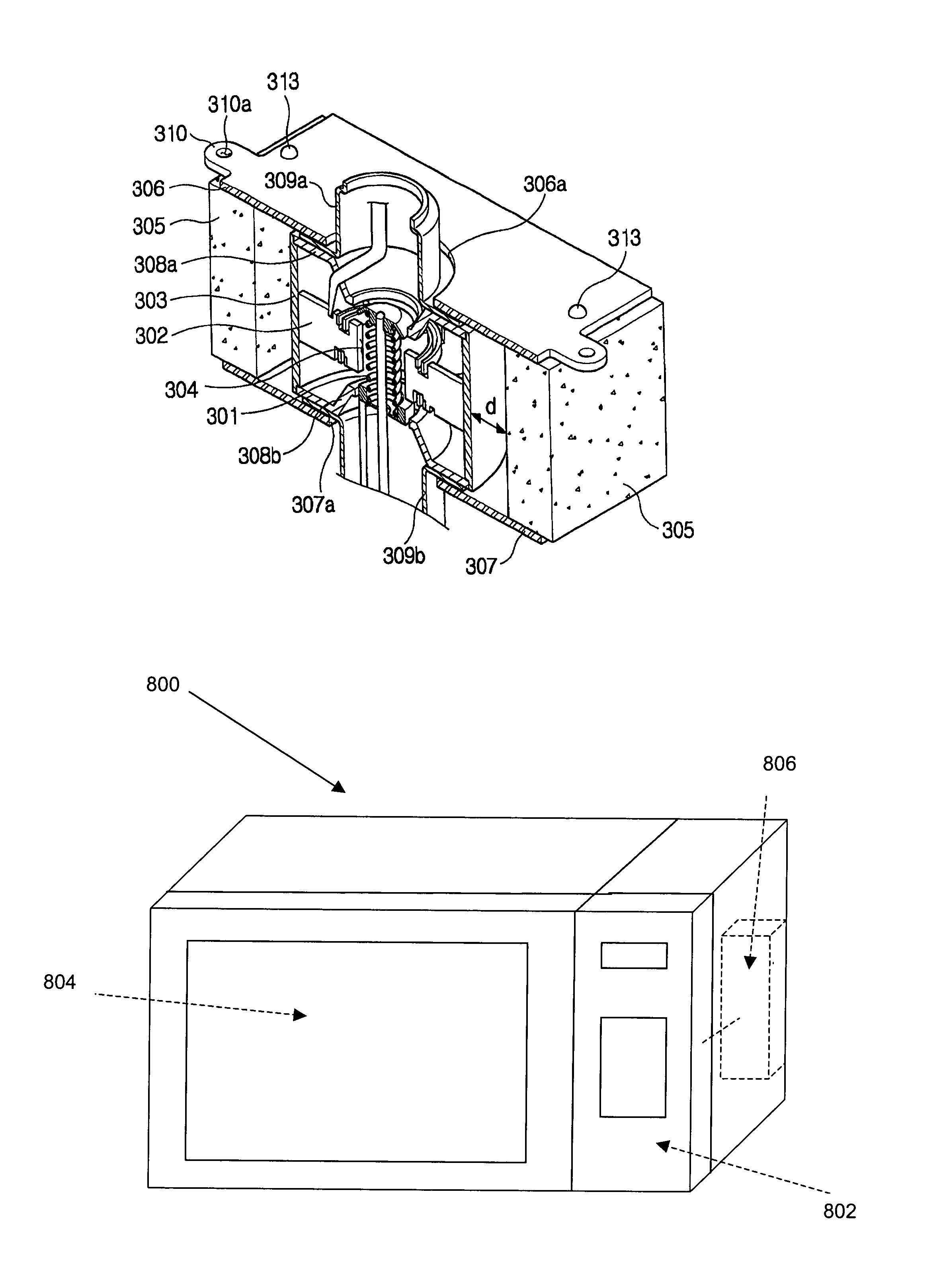
[0046]FIG. 3 is a longitudinal section showing a principal portion of a magnetron according to an embodiment of the present invention. In FIG. 3, a ring-shaped anode including a plurality of vanes forming a plurality of resonance circuits and an anode cylinder 303 is provided, a cathode including a filament 301 emitting thermions at high temperature is disposed at the axial center of the anode, and an activating / predetermined space 304 in which groups of thermions move under the influence...


PUM


Abstract

A magnetron includes a ring-shaped anode, a cathode, an activating space, at least one permanent magnet and a magnetic flux carrying unit. The ring-shaped anode forms a plurality of resonance circuits. The cathode is disposed at the axial center of the anode to emit thermions. The activating space is formed between the anode and the cathode. The at least one permanent magnet is provided beside the anode. The magnetic flux carrying unit carries magnetic flux generated by the at least one permanent magnet to the activating space. A microwave oven and / or high frequency heating apparatus may utilize the magnetron.

Description

CROSS-REFERENCE TO RELATED APPLICATIONS[0001]This application claims the benefit of Korean Application No. 2002-78049, filed Dec. 10, 2002, in the Korean Intellectual Property Office, the disclosure of which is incorporated herein by reference.BACKGROUND OF THE INVENTION[0002]1. Field of the Invention[0003]The present invention relates generally to a magnetron, and a microwave oven and a high-frequency heating apparatus, each equipped with the magnetron and more particularly, to a magnetron in which the arrangement of magnets applying magnetic flux to the activating space of the magnetron are improved, and the shapes of upper and lower yokes are changed to correspond to the improvement of the arrangement, and a microwave oven and a high-frequency heating apparatus each equipped with the same.[0004]2. Description of the Related Art[0005]A construction of a conventional magnetron is described with reference to an accompanying drawing. As illustrated in FIG. 1, in the conventional magn...

Claims


Application Information

Patent Timeline
Patent Type & Authority Patents(United States)
IPC IPC(8): H01J25/50H05H7/02F24C7/02G01S7/282H01J23/10H01J23/15H01J25/587H05B6/64H05B6/66H05B6/72
CPCH01J23/10H05B6/72H01J25/587H01J23/15
Inventor SHON, JONG-CHULLRAYSKIY, BORIA V.HA, HYUN-JUN
Owner SAMSUNG ELECTRONICS CO LTD
Why Eureka
Try Eureka