
Injection site for male luer or other tubular connector

a tubular connector and injection site technology, applied in the direction of catheters, intravenous devices, other medical devices, etc., can solve the problems of not being suitable for all uses, the site on a flexible tube set may not fit with the medic design, and the needle cannot connect with the luer connection

Active Publication Date: 2006-04-11
B BRAUN MEDICAL
View PDF163 Cites 102 Cited by
  • Summary
  • Abstract
  • Description
  • Claims
  • Application Information

AI Technical Summary

Benefits of technology

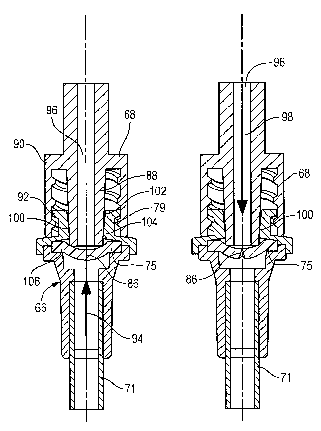
[0011]Advantages of this include the fact that, with such limited penetration, the connector tube will not project far into the area inside of the elastomeric wall, which may comprise a blood flow path. Such penetration can cause turbulence, and can reduce the laminar flow of blood through the blood flow path, which is undesirable. Also, such limited penetration, while effective to achieve fluid flow through the elastomeric wall, permits a smaller device to be designed and used, compared with systems where full penetration of the elastomeric wall by the connector tube takes place. Also, as is illustrated in the preferred embodiment of FIG. 13, there are laminar flow advantages available to a connector tube that does not fully penetrate the elastomeric wall. The almost-penetrated elastomeric wall serves as a transition and flow guide between the annular end face of the connector tube and the lumen wall of the adjacent connector bore. In typical male / female connector sets, the flow path must exhibit a “step out” from the connector tube to the adjacent bore with significant pressure losses, dependant on the size of the annular face. By this invention, such a step is largely avoided, thus reducing turbulence.
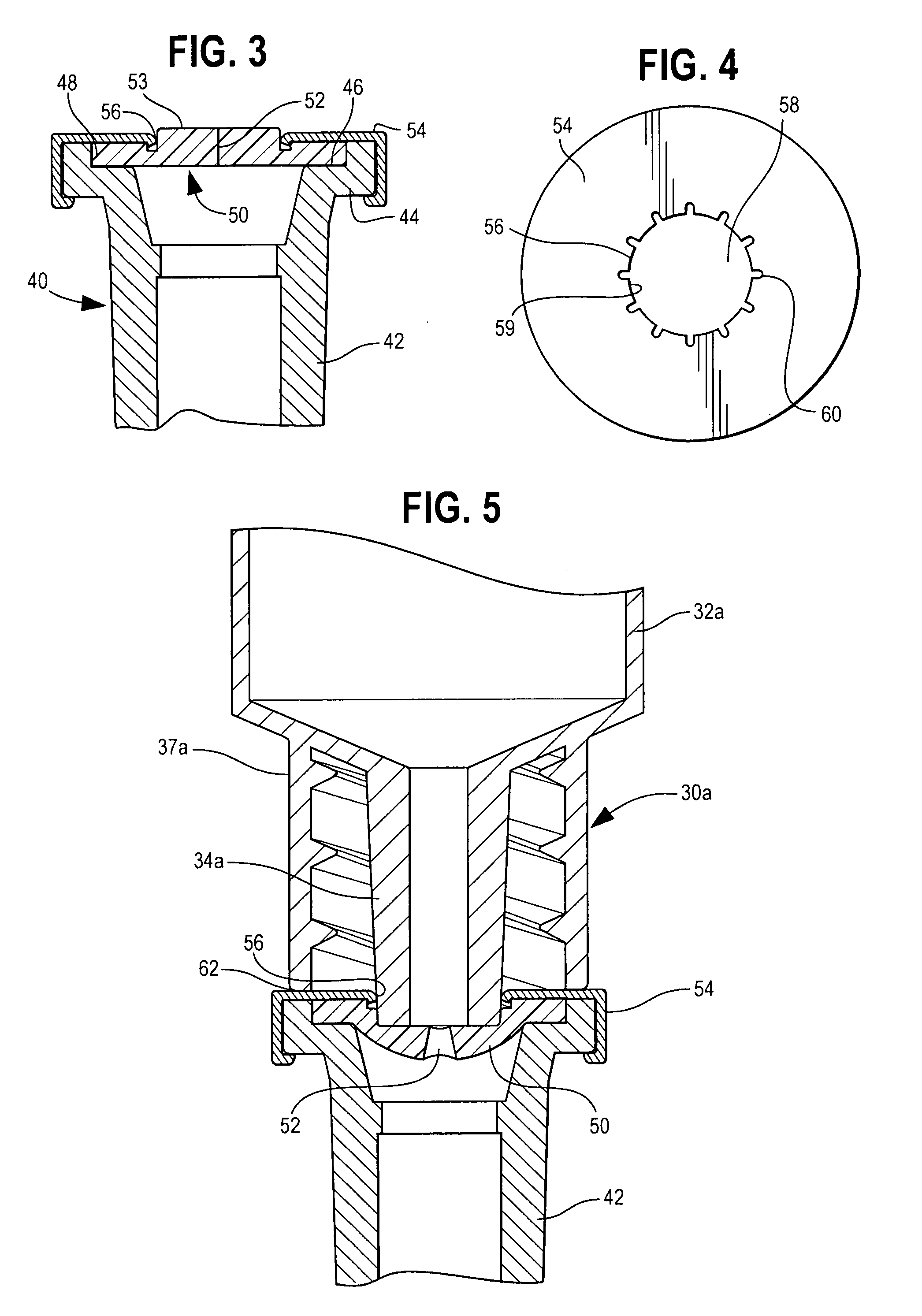
[0012]Preferably, the retention zone may be ring-shaped, and may have an axial depth (i.e. its dimension in the generally axial direction of the retained connector tube) of no more than about 3 mm. In some embodiments, the retention wall may comprise a transverse wall having an aperture that defines the central opening with a thickness of no more than about 1 mm, so that the edge of the wall that defines the central opening can dig into and deform a portion of the retained connector tube, which connector tube may typically be conical in shape. As one advantage of such a configuration, the molding tolerance of the respective parts can be relatively low when compared with a luer connection. For example, it is generally necessary for the retained connector tube to be positioned in its engaged and retained position with its tip extending into engagement with the elastomeric wall to deflect the elastomeric wall, (or optionally to penetrate it) to open the perforation of the elastomeric wall so that flow communication can take place through the elastomeric wall and the retained connector tube. However, the overall dimensions and the longitudinal position of the connector tube may have a certain amount of variability (tolerance) and it still may be advanced into engagement with the elastomeric wall, with material deformation taking place by engagement of the connector tube and the retention zone and the necessary position achieved. Thus, the parts of the device are easier to manufacture.
[0013]This is particularly important in the case where the retained connector tube is part of an ISO male luer lock connector, where the luer of such connectors only extends a short distance beyond its locking sleeve (such as 2.1 to 3.5 mm), and the advancement into engagement with an elastomeric wall is thus of limited distance. In this embodiment, the male luer does not penetrate completely through the elastomeric wall, but merely may displace it by a distance sufficient to stretch open the perforation of the elastomeric wall. Upon such advancement, the retention zone surrounding the central opening forcefully engages the male luer of the luer lock connector, with deformation of material resulting through such engagement in one, or the other, or both parts, to increase the strength of retention between the retention wall and the male luer connector tube, so that the natural resilience of the displaced elastomeric wall does not force expulsion of the connector tube from the retention zone, and a stable, open flow path is created. This arrangement is especially good for connectors used in blood flow tubing, since a turbulence and clot promoting male luer tip in the blood flow path is avoided.
[0023]As stated above, locking systems may be utilized as additional structure for connection so that accidental connector separation can be further eliminated as a risk.
[0024]Alternatively, the retention wall and retention zone described above may also be made of a fairly resilient material, so that it does some or all of the deformation, when engaging with the retained connector tube, to have the effect of increasing strength of retention between the retention wall and the connector tube.
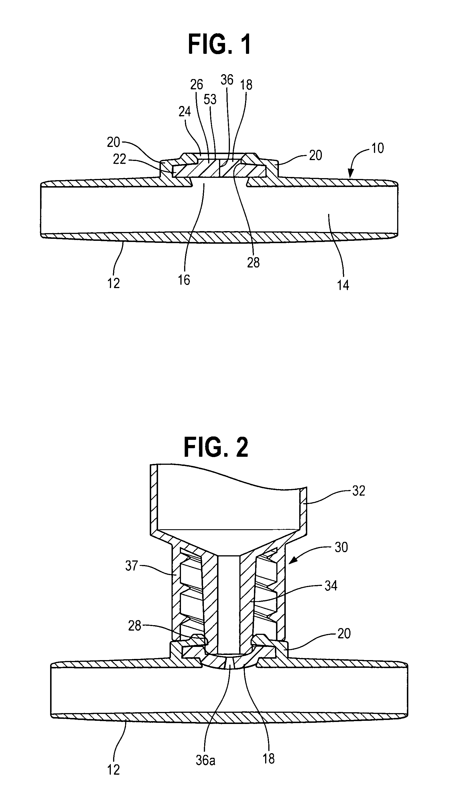
[0031]Furthermore, the central area of the elastomeric wall may typically have a thickness of no more than 3 mm. Also, it is generally preferred for the second upper surface (of the central portion of the elastomeric wall) to have a level that is above the level of the first, upper surface of the closed loop area against which the male luer lock connector may abut. This provides more distance of displacement of the elastomeric wall when it is opened, when compared with prior art injection sites.

Problems solved by technology

As a disadvantage, a needle cannot connect with a luer connection and vice versa.
However this device is not suitable in all uses.
For example, an injection site on a flexible tube set may not fit with the Medic design because the Medic device is too long, and impinges the opposite wall of an injection site carried on tubing, having an entry direction perpendicular to the axis of the tubing.
As a further disadvantage, there may be a need to make a connection through an elastomeric diaphragm injection site using a tube which is terminated in a male luer connector.
Present means for doing this are cumbersome.

Method used


Image

  • Injection site for male luer or other tubular connector
  • Injection site for male luer or other tubular connector
  • Injection site for male luer or other tubular connector

Examples


Embodiment Construction

[0005]In accordance with this invention, an injection site is provided as part of a medical device which has an interior for containment of a fluid (liquid or gas). For example, the medical device may be a drug vial or container which utilizes the injection site of this invention, or it can be a tubing set having a main flow path for blood, parenteral solution, gases, or the like, to permit access preferably either by a male luer (luer slip or luer lock) connector or other type of tubular probe, without any intermediate device as in the prior art, such access being to the flow path of the tube set or the interior of any other container. Preferably, access through the injection site is also available as well by a needle, sharp or blunt.

[0006]An opening is defined into the interior of the medical device, with an elastomeric wall forming a fluid / air tight barrier across the opening, preferably both at positive and negative pressures relative to atmosphere. The elastomeric wall typicall...


PUM


Abstract

A medical device has an interior for containment of fluids; an opening into the interior, an elastomeric wall comprising a fixedly placed, flexible barrier across the opening; and a retention wall positioned adjacent to a peripheral portion of the elastomeric wall. The retention wall defines a central opening and has a generally rigid retention zone surrounding the central opening, to engage and retain a connector tube which is advanced into the central opening to displace the elastomeric wall and to open a flow aperture through the elastomeric wall, for flow through the wall and connector tube. One of the retention zone and connector tube are made of a material of sufficient hardness that material of the other engaging member is deformed by engagement therewith, which increases the strength of retention between the retention wall and the connector tube.

Description

BACKGROUND OF THE INVENTION[0001]Tubing sets for the transfer of medical fluids such as blood or parenteral solution generally comprise flexible plastic tubing with end connectors, which are often luer-type connectors. Injection sites are often carried on the tubing at the ends of, or between the ends of, the tubing sets, comprising an elastomeric diaphragm or bung which is carried in a housing in typically compressed or restrained fashion, so that a needle can resealably penetrate the elastomeric bung and communicate with the interior of the tubular set, for administration of medicines and the withdrawal of medical samples such as blood. Also, in the field of extracorporeal blood transport, in which blood is conveyed to and from an extracorporeal blood processing device such as a dialyzer or an aphaeresis apparatus, such an injection site may also be used to add parenteral solution such as normal saline.[0002]As a disadvantage, a needle cannot connect with a luer connection and vic...

Claims


Application Information

Patent Timeline
IPC IPC(8): A61M37/00A61M5/00A61M5/14A61M39/02A61M39/04A61M39/26
CPCA61M39/02A61M39/26A61M39/045
Inventor UTTERBERG, DAVID S.SCHNELL, WILLIAM J.BELL, DAVID
Owner B BRAUN MEDICAL
Learn More