Optical fiber cleaver

a technology of optical fiber and cleaver, which is applied in the direction of paper/cardboard containers, tobacco, instruments, etc., can solve the problems of inconvenient manufacture and purchase of many additional parts, unsatisfactory cleaving of optical fiber, and inability to work satisfactorily with fiber cleaver,

Inactive Publication Date: 2006-04-11
LEVITON MFG
View PDF35 Cites 22 Cited by
  • Summary
  • Abstract
  • Description
  • Claims
  • Application Information

AI Technical Summary

Benefits of technology

[0010]The present invention resides in a device for cleaving optical fibers. The device generally includes a housing with an internal chamber, a fiber alignment member removably connected to the housing and a fiber cutting member supported by the housing. The fiber alignment member has an opening, and when the alignment member is connected to the housing the opening extends between an outward end opening exterior of the housin

Problems solved by technology

Unacceptable loss of light energy at a coupling is detrimental to most transmissions and is consequently undesirable.
Further, if the diameter or length of the connector ferrule used for a particular type connector should not be the proper size, the fiber cleaver may not work satisfactorily, requiring the use of another fiber cleaver with the proper size and located housing opening and positioning component.
It is undesirable to provide several different fiber cleavers for each technician in the field to

Method used


Image

  • Optical fiber cleaver
  • Optical fiber cleaver
  • Optical fiber cleaver

Examples


Embodiment Construction

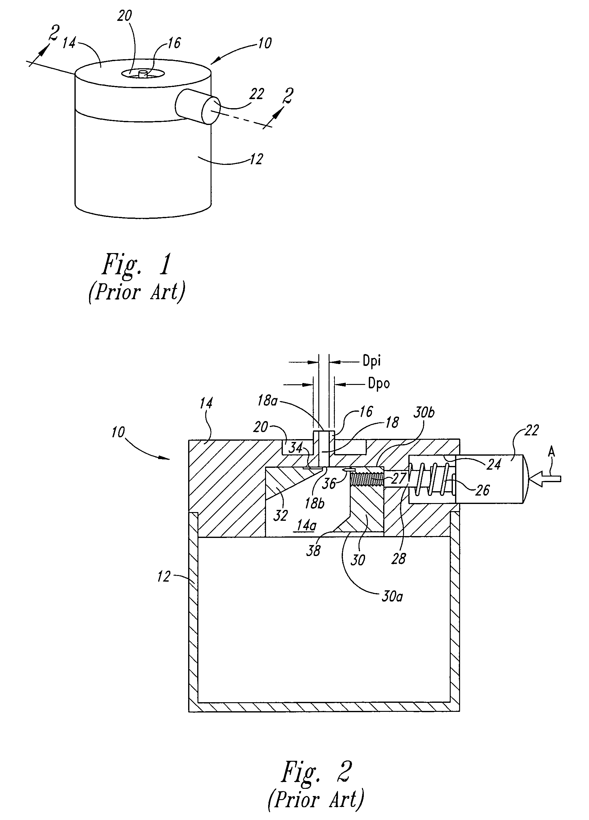
[0053]A fiber cleaver 10 of the prior art designed for use with fiber optic connectors is shown in FIG. 1. The fiber cleaver 10 comprising a housing assembly 14 having a housing port 16. The housing assembly 14 has a receptacle 12 attached thereto that collects severed ends of cleaved fibers.

[0054]The housing assembly 14 is shown in greater detail in FIG. 2. In the depicted embodiment, the housing port 16 has a tubular shape with an outer diameter, Dpo, and an inner diameter, Dpi. The housing port 16 has an elongated port opening 18 with a first end 18a and a second end 18b. An annular recess 20 is machined into the housing assembly 14, which is made of aluminum or other suitable material, and the recess extends about the housing port 16. The housing assembly 14 is shown in FIG. 2 with the receptacle 12 affixed to the housing assembly by friction fit, threaded connection, or other suitable connection. The housing assembly 14 contains a housing chamber 14a in which occurs bending and...


PUM

PropertyMeasurementUnit
Lengthaaaaaaaaaa
Forceaaaaaaaaaa
Electrical resistanceaaaaaaaaaa

Abstract

A device for cleaving optical fibers having a housing with an internal chamber, a fiber alignment member removably connected to the housing and a fiber cutting member supported by the housing. The alignment member has an opening sized to receive the ferrule of a fiber optic connector and has a stop proximate to the inward end of an opening to engaged the ferrule distal end. The alignment member is quickly interchangeable with another sized and arranged to handle the ferrule of a different type or size connector. The opening is sized to receive ferrule with an optical fiber to be cleaved, and permits the fiber to extend inward beyond the inward end of the opening and into the housing internal chamber. The fiber cutting member is mounted to the housing to cleave the fiber inserted into the opening and cause separation of a cut end of the fiber within the housing internal chamber, and is quickly removable for replacement when the alignment member is disconnected from the housing if a blade thereof is damaged or worn. The alignment member has a user operable lock to unlock the alignment member from the housing. The lock has a release positioned within the housing internal chamber for access by a user through a housing opening sized to provide access to the housing internal chamber. An endcap closes the housing opening and hold a spare fiber cutting member.

Description

TECHNICAL FIELD[0001]The present invention relates generally to a device for cleaving optical fibers, and more particularly, for cleaving optical fibers for use with different connector types while allowing replacement of damaged cleaving blades.BACKGROUND OF THE INVENTION[0002]Optical fibers are frequently used in communications systems, generally, where light energy is transmitted very long distances with little or no energy losses. Devices coupled to optical fibers and coupling of optical fibers together require cutting and subsequent connecting of the optical fibers. Unacceptable loss of light energy at a coupling is detrimental to most transmissions and is consequently undesirable.[0003]A junction between light fibers has generally a glass-to-glass interface where one fiber precisely abuts another fiber to minimize energy losses and signal distortions introduced at these junctions. Miles of optical fibers are installed in locations of varying conditions that demand tools to cle...

Claims


Application Information

Patent Timeline
IPC IPC(8): B26F3/00G02B6/25G02B6/38
CPCG02B6/25G02B6/3863Y10T83/0333Y10T225/314Y10T225/321Y10T225/371
Inventor ITANO, MICHAEL M.LANG, III, HARLEY B.LUENOW, THOMAS J.MCNUTT, PATRICK S.SILBAUGH, MICHAEL S.
Owner LEVITON MFG
Why Eureka
Try Eureka