
Fiber optic cable for use in harsh environments

a technology of fiber optic cables and harsh environments, applied in the direction of sealing/packing, instruments, borehole/well accessories, etc., can solve the problems of reducing the overall cost of down hole sensing systems, limiting the length of cable that may be transported on a spool using conventional means, and clogging the cabl

Active Publication Date: 2006-04-04
WEATHERFORD TECH HLDG LLC
View PDF21 Cites 81 Cited by
  • Summary
  • Abstract
  • Description
  • Claims
  • Application Information

AI Technical Summary

Benefits of technology

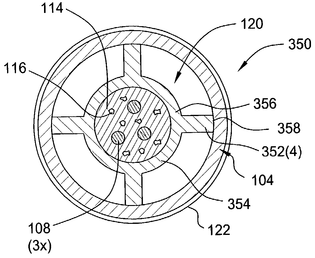
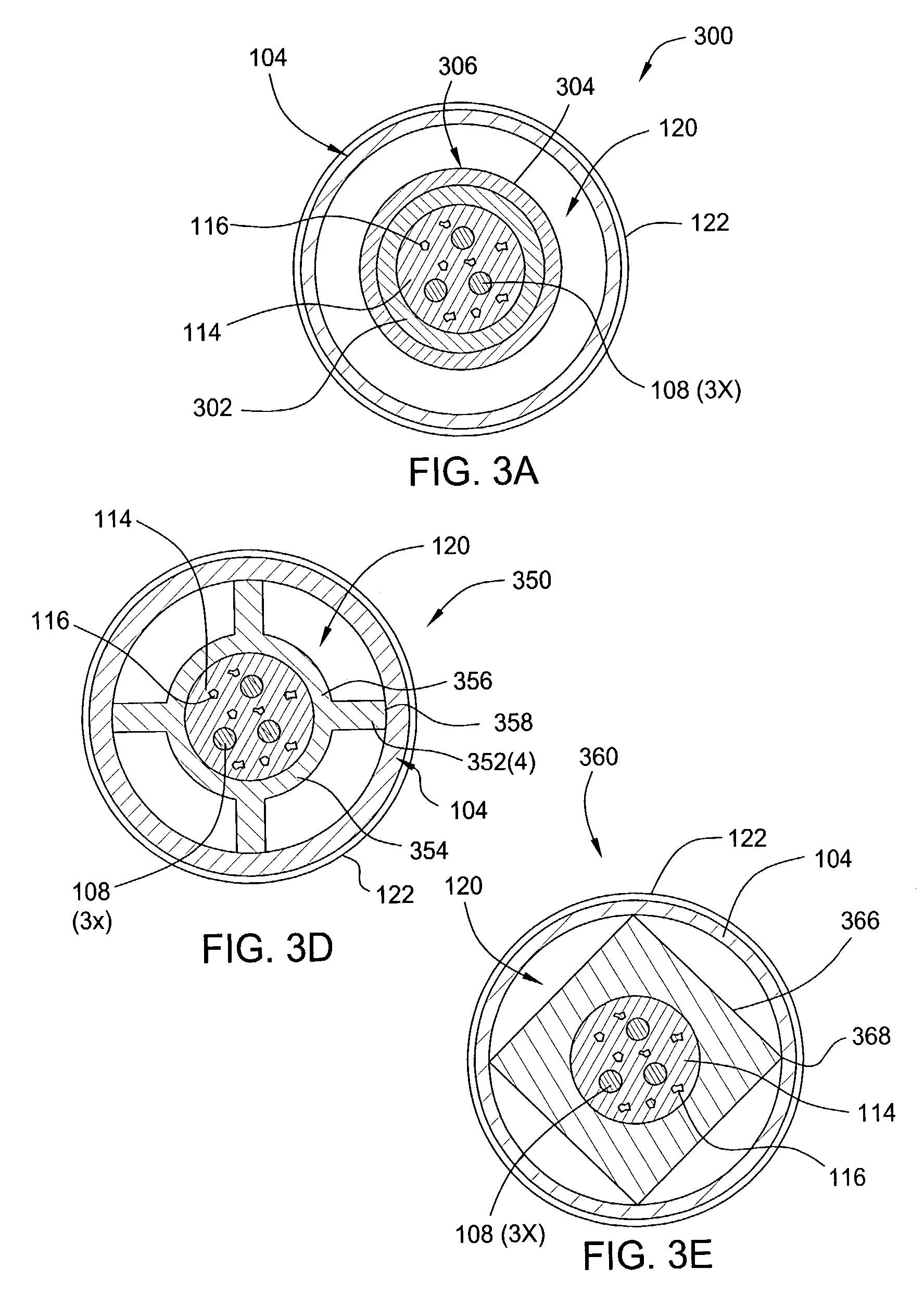
The patent text describes fiber optic cables that can be used in harsh environments such as down hole oil and gas well applications. The cables have a special design to protect the optical fibers from corrosion. One design has a metal outer tube that makes intermittent contact with the inner tube where the optical fibers are placed. Another design has the optical fibers placed in a polymer tube with fins sticking out from it. These designs make the cables stronger and more durable for use in oil field applications.

Problems solved by technology

Although this cable design has shown itself to be a robust and reliable means for providing transmission of optical signals in harsh environments such as oil and gas wells, the cable is one of the higher cost contributors to the overall cost of down hole sensing systems.
Additionally, as the diameter of the cable is typically about one-quarter inch, the length of cable that may be transported on a spool using conventional means is limited to about 20,000 feet of cable.
Thus, in many down hole well applications, only a single sensor may be coupled to a length of cable coming off a single spool, as the residual length of cable on the spool is not long enough for another down hole application without splicing on an addition cable segment.

Method used


Image

  • Fiber optic cable for use in harsh environments
  • Fiber optic cable for use in harsh environments
  • Fiber optic cable for use in harsh environments

Examples


Embodiment Construction

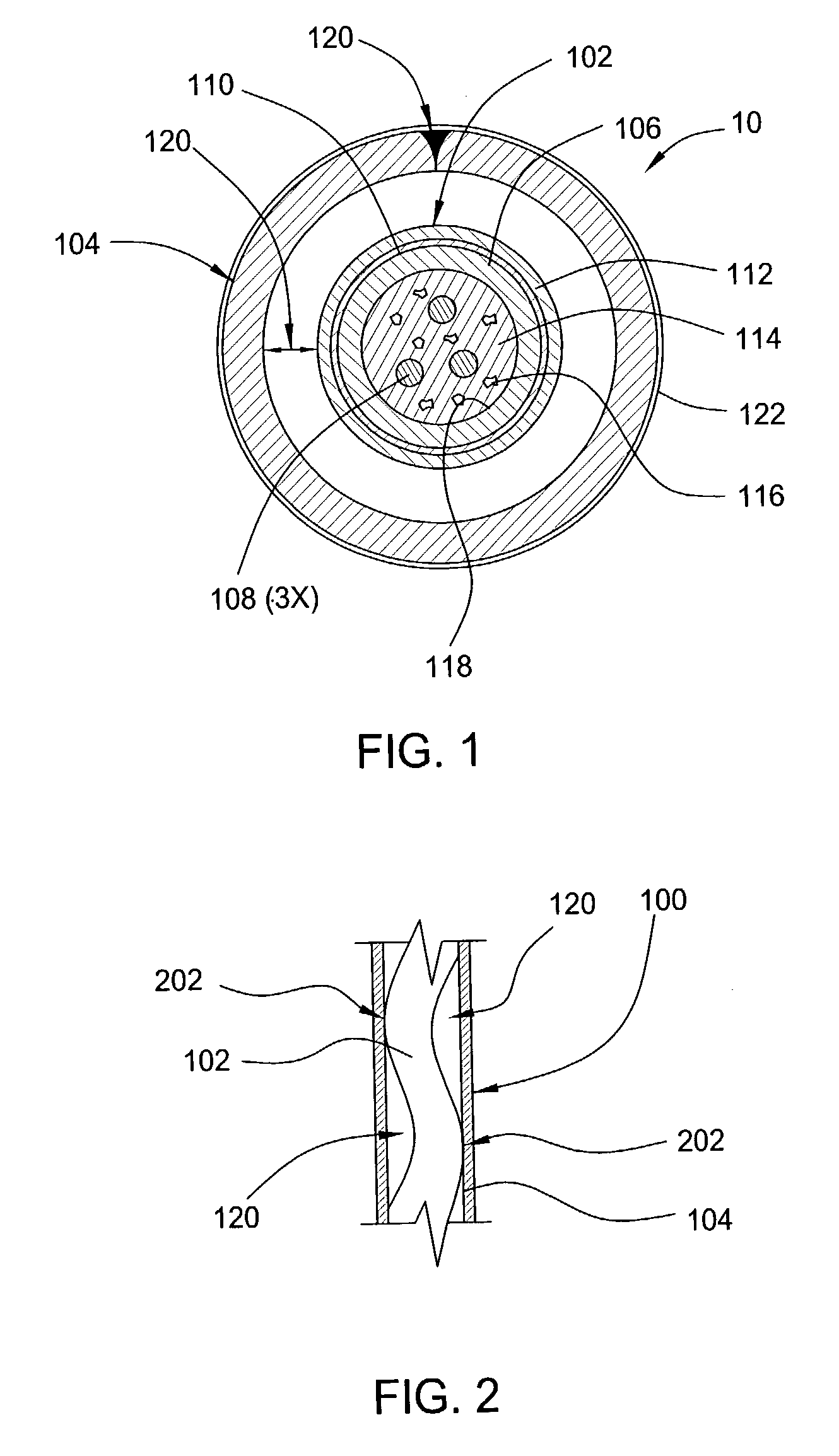
[0019]FIG. 1 is one embodiment of a fiber optic cable 100 suitable for use in down hole oil and gas well applications. The cable 100 comprises a fiber in metal tube (FIMT) core 102 disposed in a protective outer tube 104. The FIMT 102 comprises an inner tube 106 surrounding one or more optical fibers 108, three of which are shown in the embodiment depicted in FIG. 1.

[0020]The inner tube 106 is fabricated from a corrosion resistant material. Examples of suitable corrosion resistant metal alloys include, but are not limited to, 304 stainless steel, 316 stainless steel, INCONEL® 625 and INCOLOY® 825, among others. Examples of suitable plastics include, but are not limited to fluoropolymers, ethylene-chlorotrifluoroethylene, fluoroethylenepropylene, polyvinylidene fluoride, polyvinylchoride, HALAR®, TEFLON® and TEFZEL®, among others. The diameter of the inner tube 106 may be in the range of about 1.1 to about 2.6 mm, and in an exemplary embodiment of the invention is about 2.4 mm. Altho...


PUM


Abstract

Fiber optic cables suitable for use in harsh environments such as down hole oil and gas well applications and methods for fabricating the same have been provided. In one embodiment, an optic cable suitable for down hole oil field applications comprises one or more optical fibers disposed in an inner tube and a corrosion resistant metal outer tube disposed over the inner tube, where the inner and outer tubes make intermittent contact. In another embodiment, an optic cable suitable for down hole oil field applications comprise one or more optical fibers disposed in a polymer tube having fins extending therefrom.

Description

BACKGROUND OF THE INVENTION[0001]1. Field of the Invention[0002]Embodiments of the invention generally relate to fiber optic cables for use in harsh environments such as down hole gas and oil well applications.[0003]2. Background of the Related Art[0004]With advancements in the area of fiber optic sensors for use in harsh environments, there is an increasing need for fiber optic cables compatible with the harsh environmental conditions present in down hole oil and gas well applications. For example, fiber optic cables utilized in down hole sensing applications must be able to operate reliably in conditions that may include temperatures in excess of 300 degrees Celsius, static pressures in excess of 20,000 pounds per square inch (psi), vibration, corrosive chemistry and the presence of high partial pressures of hydrogen. As the sensors utilized in down hole applications may be positioned at depths up to and exceeding 20,000 feet, the fiber optic cable coupled thereto must be designed...

Claims


Application Information

Patent Timeline
Patent Type & Authority Patents(United States)
IPC IPC(8): G02B6/44G02B6/10G08C23/06
CPCG02B6/4492G02B6/4429G02B6/44382G02B6/443G02B6/4436
Inventor DOWD, EDWARD M.IVES, JR., MILTON E.
Owner WEATHERFORD TECH HLDG LLC
Learn More