
Optical E-field modulation using a Mach-Zehnder interferometer

a technology of optical e-field modulation and interferometer, which is applied in the field of optical signal transmitters, can solve the problems of high cost, high cost of laser current control, and the inability to obtain the desired frequency modulation of the laser, and achieve the effect of facilitating the precompensation of optical impairment and low cos

Inactive Publication Date: 2006-04-04
CIENA
View PDF44 Cites 55 Cited by
  • Summary
  • Abstract
  • Description
  • Claims
  • Application Information

AI Technical Summary

Benefits of technology

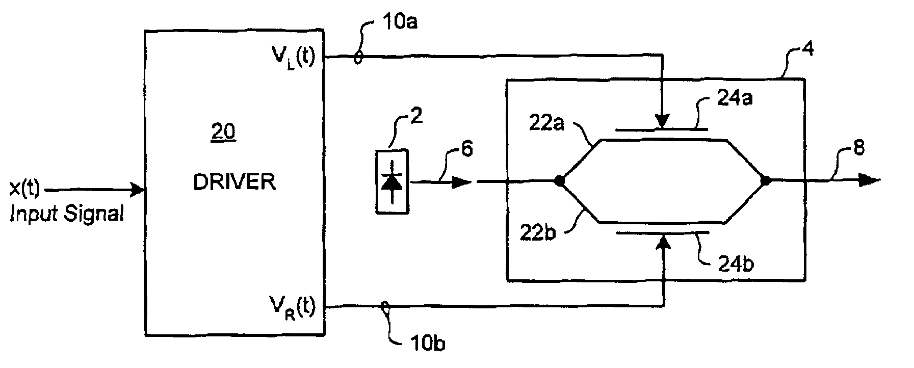
The present invention provides methods and apparatus for modulating the E-field of an optical carrier signal. This is achieved by using a Mach-Zehnder modulator with a pair of independently controllable branches, which can perform complex modulation of the E-field of the optical carrier. This functionality can be used to facilitate precompensation of optical impairments of an optical communications system. The technical effect of the invention is to provide a cost-effective solution for complex modulation of the E-field of an optical carrier.

Problems solved by technology

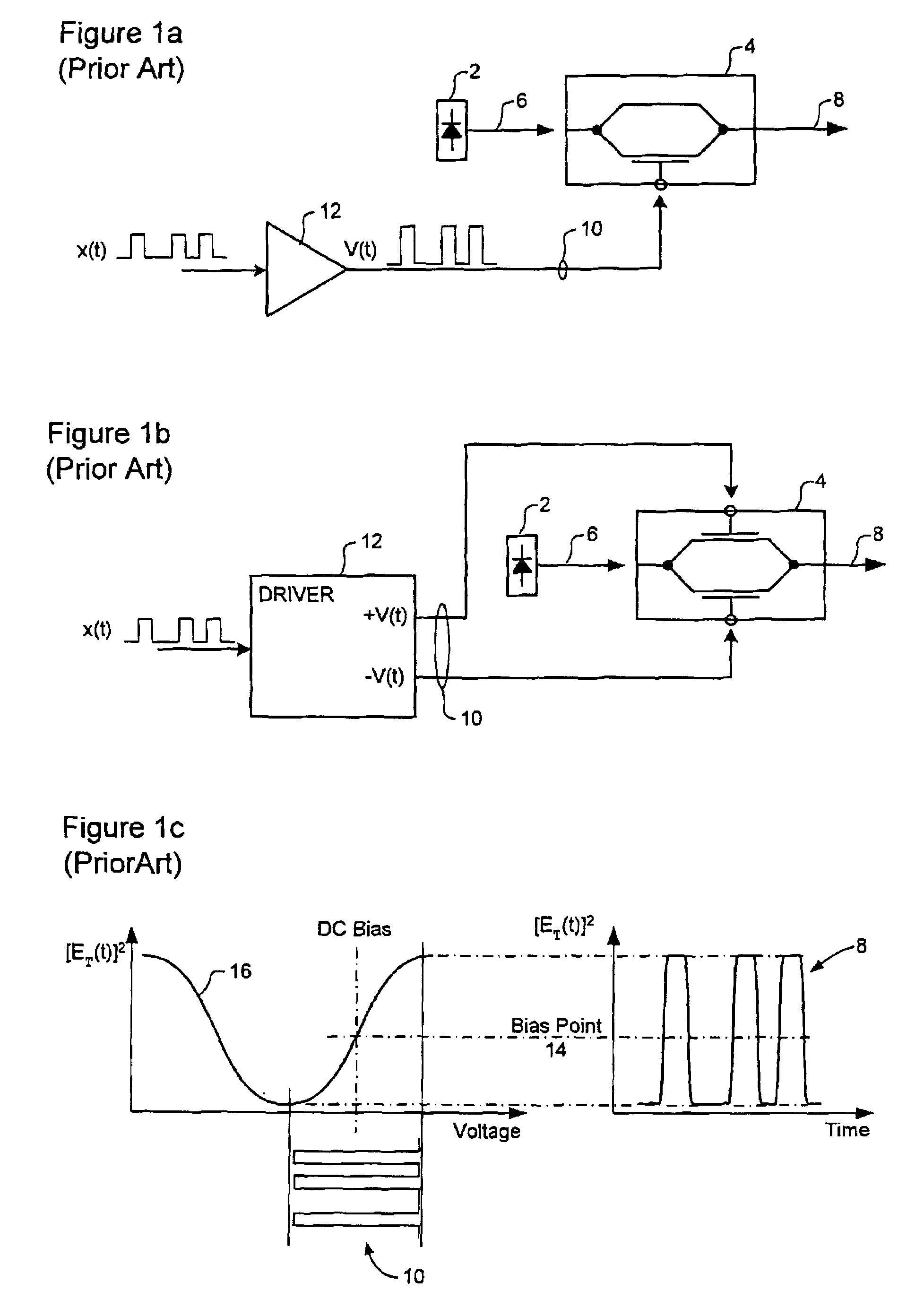
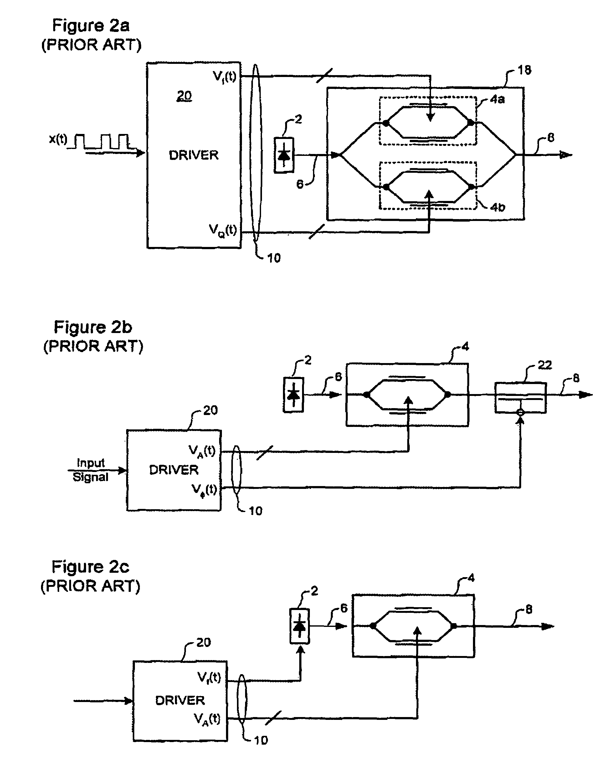
A limitation of the optical signal synthesizers illustrated in FIGS. 1a–1c, is that they are designed to modulate only a single dimension (i.e. amplitude or phase) of the CW optical carrier signal 6 generated by the narrow-band laser 2.
However, the solutions of FIGS. 2a and 2b are expensive, because multiple devices are required.
The solution of FIG. 2c requires only a single amplitude modulator 4, but suffers a disadvantage that the laser is current-controlled.
In some cases, obtaining the desired frequency modulation of the laser 2 may require very large and / or very rapid changes in the drive signal voltage.
This increases the cost of the driver circuit 20, and may result in the production of unwanted noise.

Method used


Image

  • Optical E-field modulation using a Mach-Zehnder interferometer
  • Optical E-field modulation using a Mach-Zehnder interferometer
  • Optical E-field modulation using a Mach-Zehnder interferometer

Examples


Embodiment Construction

[0024]The present invention provides methods and apparatus for modulating the E-field of an optical carrier signal. Embodiments of the invention are described below, by way of example only, with reference to FIGS. 3–5.

[0025]For the purposes of understanding the present invention, it is useful to consider a representation of the total optical E-field E(t) as a vector confined to a plane and emanating from a fixed origin, where the length of the vector gives the amplitude of the E-field at any instant (t), and the direction of the vector gives the phase of the field at any instant (t). Within this construction, we consider two basis sets. The first basis set is a Cartesian coordinate system centered on the E-field origin. In this Cartesian representation, the total E-field E(t) is decomposed along the orthogonal h-Phase (I) and Quadrature (Q) direction. The second basis set is a polar coordinate system, again sharing its origin with that of the E-field vector. In this poles representa...


PUM

PropertyMeasurementUnit
phase anglesaaaaaaaaaa
phase responseaaaaaaaaaa

Abstract

A method for modulating the E-field of an optical carrier signal utilizes a Mach-Zehnder modulator having a pair of independently controllable branches. A pair of independent branch drive signals VL(t) and VR(t) are derived. Each branch of the MZ modulator is driven with a respective one of the independent branch drive signals. By this means, a low cost conventional MZ modulator (interferometer) can be used to perform complex modulation of the E-field of the optical carrier. In some embodiments, this functionality is used to facilitate precompensation of optical impairments of an optical communications system.

Description

CROSS-REFERENCE TO RELATED APPLICATIONS[0001]This application is a Continuation-in-Part of Applicant's co-pending U.S. patent applications Ser. Nos. 10 / 307,466 filed Dec. 2, 2002; and Ser. No. 10 / 405,236 filed Apr. 3, 2003. This application also claims priority of International Patent Application No. PCT / CA03 / 01044 filed Jul. 11, 2003.MICROFICHE APPENDIX[0002]Not Applicable.TECHNICAL FIELD[0003]The present invention relates to optical signal transmitters for optical communications systems, and in particular to optical E-field modulation using a Mach-Zehnder (MZ) interferometer.BACKGROUND OF THE INVENTION[0004]In the optical communications space, various techniques are used to synthesize an optical communications signal for transmission. A popular technique utilizes a laser 2 coupled to an external optical modulator 4, as shown in FIG. 1a. The laser 2 generates a narrow-band continuous wave (CW) optical carrier signal 6 having a desired wavelength. The optical modulator 4 operates to...

Claims


Application Information

Patent Timeline
Patent Type & Authority Patents(United States)
IPC IPC(8): G02F1/03G02F1/07H04B10/18
CPCG02F1/225H04B10/505H04B10/25137
Inventor MCGHAN, DOUGLASO'SULLIVAN, MAURICEBEAULIEU, YVES
Owner CIENA
Learn More