
Portable boring and welding machine

a welding machine and portability technology, applied in the direction of drilling/drilling components, welding apparatus, woodworking apparatus, etc., can solve the problems of poor machine performance, inconvenient operation, and inability to meet the requirements of the job, so as to achieve the effect of simple construction, practicality and function

Inactive Publication Date: 2006-04-04
SIR MECCANICA
View PDF14 Cites 17 Cited by
  • Summary
  • Abstract
  • Description
  • Claims
  • Application Information

AI Technical Summary

Benefits of technology

[0011]The aim of the present invention is therefore to overcome the above mentioned disadvantages by providing a portable boring and welding machine that is functional, practical and simple in construction.

Problems solved by technology

These triple-motor machines are extremely complex on account of the large number of components and, in an attempt to provide a simplified solution, machines with only two motors have been constructed.
Twin-motor machines, although they are much more simple, are not entirely satisfactory: transmission of rotational motion is accomplished by flexible transmission means, such as elastic belts, whose tension must be kept at a defined optimum level using special tensioning devices.
The above mentioned tensioning devices are therefore unable to guarantee the correct belt tension for all the different working conditions, which leads to poor machine performance.
Another drawback closely connected with the use of flexible means for transmitting rotational motion is due to the vibrations created during machining which are propagated from one machine part to another and which have a negative effect on the flexible transmission means.

Method used


Image

  • Portable boring and welding machine
  • Portable boring and welding machine
  • Portable boring and welding machine

Examples


Embodiment Construction

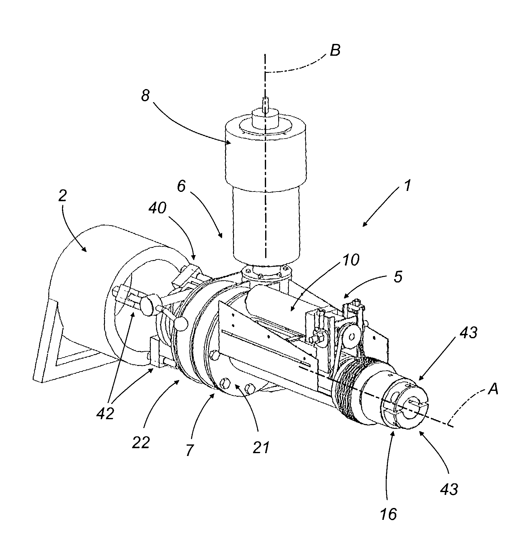
[0018]With reference to the accompanying drawings, the numeral 1 denotes in its entirety a portable boring and welding machine used to recondition crankpin bores or seats, cylinder liners, or, in general, the seats of bearings for rotating machine parts, hereinafter referred to as workpieces and labeled 2 in their entirety.

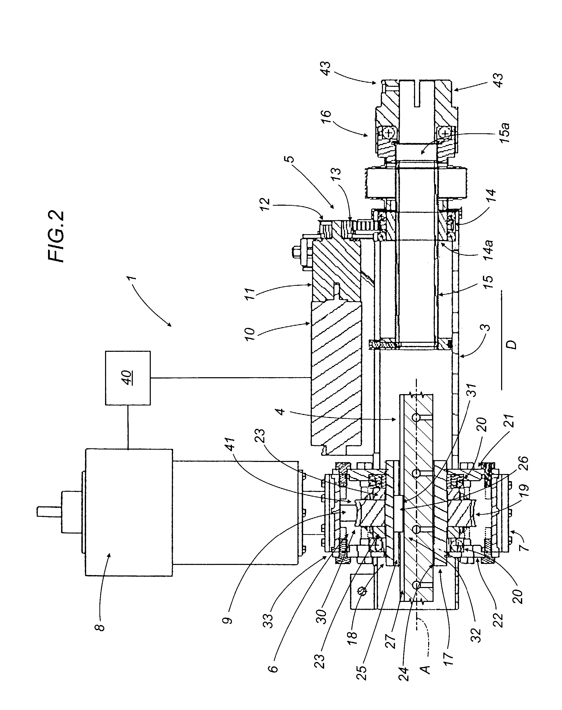
[0019]As illustrated in FIG. 1, showing a perspective exploded view without guards and covering elements and handles for transportation, the machine 1 comprises a tubular mounting structure 3, a tool shaft 4, a tool shaft feed unit 5 housed in the tubular mounting structure 3 and a drive unit 6 for rotating the tool shaft 4.

[0020]The shaft 4 extends along a longitudinal axis A which also constitutes the axis of rotation of the shaft 4.

[0021]The rotational drive unit 6 of the tool shaft 4 is housed inside a casing 7 connected to a first, front end 3a of the mounting structure 3.

[0022]In the present specification, the term tool shaft is used to mean either the shaft...


PUM

PropertyMeasurementUnit
Stiffnessaaaaaaaaaa

Abstract

A portable boring and welding machine includes a tool shaft adapted to mount tools for boring and welding workpieces. The shaft extends along an axis and is driven by an electric motor. The motor and the shaft are connected by a helical gearwheel and worm pair, the helical gearwheel being connectable to the tool shaft, and the worm being connected to a drive shaft of the motor itself.

Description

BACKGROUND OF THE INVENTION[0001]The present invention relates to a portable boring and welding machine.[0002]In particular, the present invention relates to a portable boring and welding machine of the type normally used to recondition bores or seats for crankpins, cylinder liners, etc., directly on a machine or part of a machine without having to transport the part to be repaired to a workshop and without having to place the part on a fixed machine tool.[0003]This need is felt especially strongly when repairing the rotating parts of large construction machines such as excavators and cranes or parts of fixed installations that are difficult to dismantle and transport.[0004]A typical example of the use of a portable boring and welding machine is boring (or reaming) a bore to be reconditioned, then adding material by welding and finally finishing the bore by boring (or reaming) to restore the original dimensions and tolerances.[0005]For this purpose, machines with three drive motors ...

Claims


Application Information

Patent Timeline
IPC IPC(8): B23P23/00B23K9/04B23K28/02B23P6/00B23Q5/32B23Q9/00
CPCB23K9/048B23K28/02B23P6/00B23Q5/326B23Q9/0021Y10T408/675Y10T408/348Y10T408/68Y10T29/5107Y10T408/65Y10T408/6793Y10T29/50Y10T408/94
Inventor SIRACUSA, MASSIMO
Owner SIR MECCANICA
Learn More