Power operated running board
a running board and power technology, applied in the direction of superstructures, steps, superstructure sub-units, etc., can solve the problems of running boards often being coated with dirt and/or mud, stepping surfaces becoming slippery, and stepping surfaces to the outside elements
- Summary
- Abstract
- Description
- Claims
- Application Information
AI Technical Summary
Benefits of technology
Problems solved by technology
Method used
Image
Examples
first embodiment
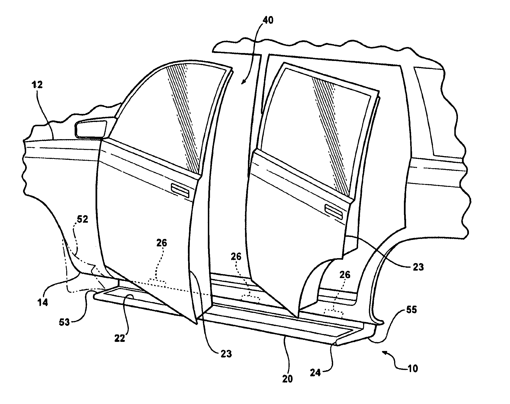
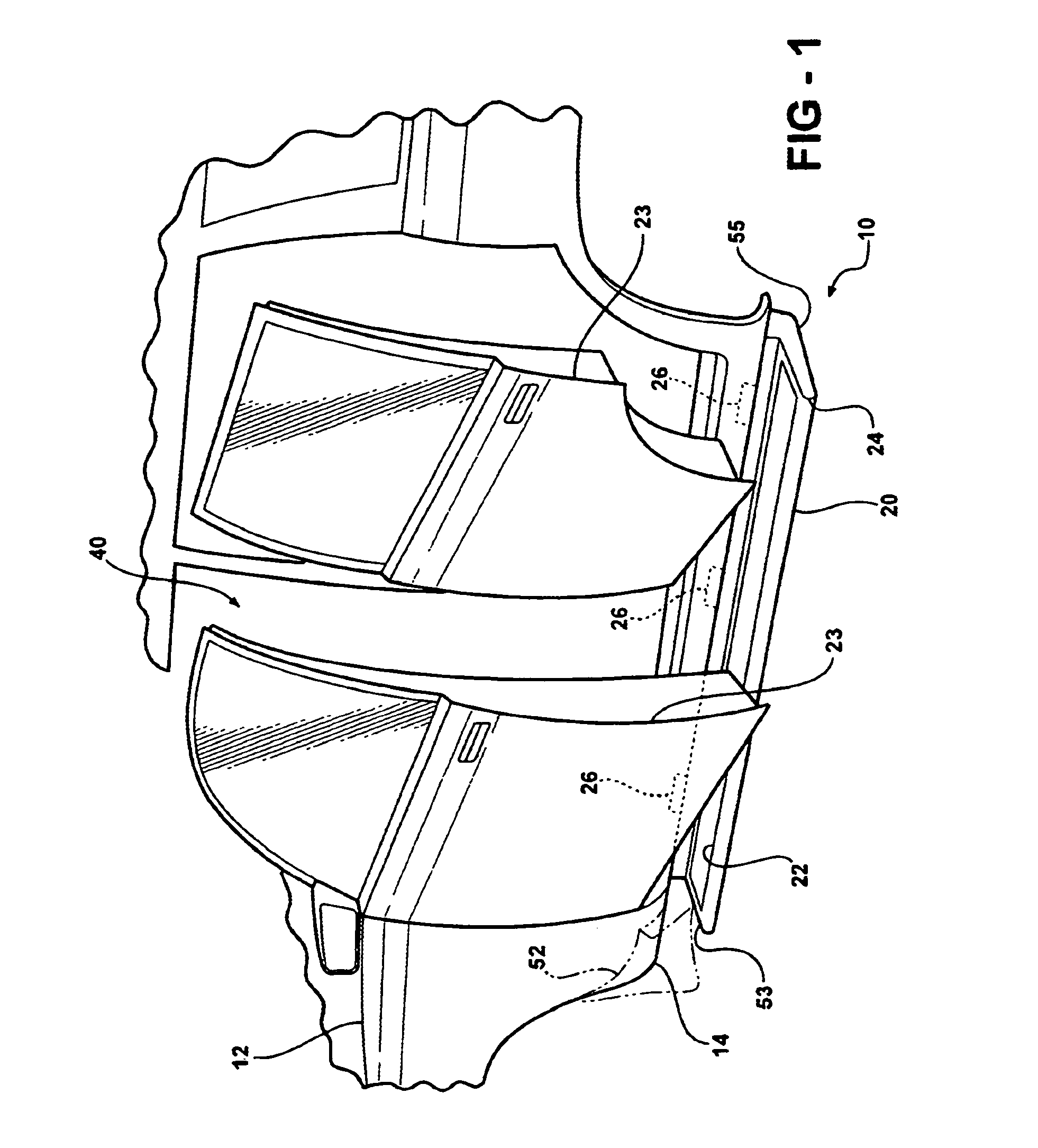
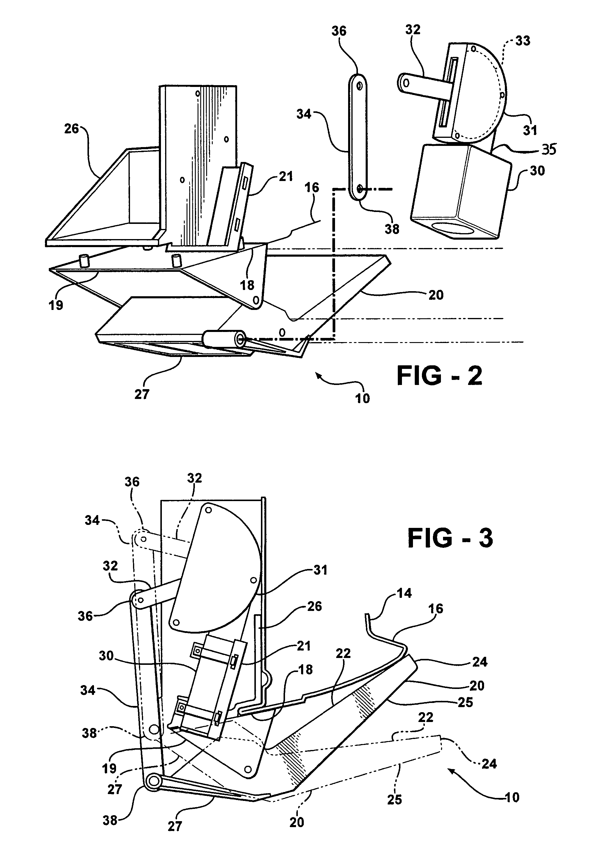
[0020]Referring to FIGS. 1–6, the invention, a running board assembly, is generally indicated at 10. The running board assembly 10 extends longitudinally alongside a motor vehicle 12. The running board assembly 10 is secured to a body 14 of the motor vehicle 12. The body 14 includes an inner rocker panel 16 and a flange 18 extending away from the inner rocker panel 16, which also extends longitudinally alongside the motor vehicle 12. A plurality of supporting brackets 19 is secured to the rocker inner panel 16 and to the flange 18 by screws or other suitable fasteners. One of the plurality of supporting brackets 19 includes a motor support bracket 21 secured thereto for supporting a motor 30.
[0021]The running board assembly 10 includes a step 20 positioned below a door 23. The step 20 defines a stepping surface 22 for supporting individuals entering or exiting the motor vehicle 12, a peripheral edge 24 extending around at least a portion of the stepping surface 22, and a contoured u...
second embodiment
[0031]Referring to FIGS. 7 and 8, wherein like primed reference numerals represent similar elements as those described above, the invention is shown wherein the motor 30′ drives a sector gear 56, which is operatively connected to the step 20′, to move the step 20′ between the stowed and deployed positions. The sector gear 56 includes an arm bracket 57 for securing the step 20′ thereto. The sector gear 56 defines a slot 58 extending between an upper slot end 60 and a lower slot end 62 thereof. The sector gear 56 also includes an arcuate, toothed portion 64 therealong.
[0032]A circle gear 68 has a toothed portion 70 and defines an aperture 72 therethrough. A bushing 74 defines an aperture 76, through which a pin 78 extends.
[0033]The motor 30′ includes a shaft 37 extending out therefrom, which extends through the aperture 72 of the circle gear 68 and rests within the slot 58 of the sector gear 56. At the same time, the toothed portion 70 of the circle gear 68 engages the arcuate, toothe...
third embodiment
[0035]Referring to FIG. 9, wherein like double primed reference numerals represent similar elements as those described above, the invention is shown including a plurality of links 84 having an upper link end 86 and a lower link end 88. The cantilever arm 27″ defines a plurality of apertures 82, which is aligned with the lower link end 88 of the plurality of links 84 to create a four bar linkage. A plurality of mounting apertures 92 defined by each of the plurality of mounting brackets 26″ are aligned with the upper link end 86 of the plurality of links 84. Thus, the plurality of links 84 interconnect the cantilever arm 27″ and the motor vehicle 12″. A linking bracket 90 is secured to the linking arm 32″ of the motor 30″ to connect the motor 30″ to the plurality of links 84, and to operatively connect the motor 30″ and the step 20″. Upon activation of the motor 30″, the plurality of links 84 moves the step 20″ between its deployed and stowed positions.
[0036]Referring to FIGS. 10 and ...
PUM
 Abstract
Description
Claims
Application Information
 - R&D
- Intellectual Property
- Life Sciences
- Materials
- Tech Scout
- Unparalleled Data Quality
- Higher Quality Content
- 60% Fewer Hallucinations
Browse by: Latest US Patents, China's latest patents, Technical Efficacy Thesaurus, Application Domain, Technology Topic, Popular Technical Reports.
© 2025 PatSnap. All rights reserved.Legal|Privacy policy|Modern Slavery Act Transparency Statement|Sitemap|About US| Contact US: help@patsnap.com


