Elastic flat tread
a flat tread, elastic technology, applied in the direction of driving belts, belts/chains/gearrings, mechanical devices, etc., can solve the problems of increasing user costs, affecting and causing cracks in elastic solid ends b>131/b>, so as to improve the durability of elastic flat treads.
- Summary
- Abstract
- Description
- Claims
- Application Information
AI Technical Summary
Benefits of technology
Problems solved by technology
Method used
Image
Examples
first embodiment
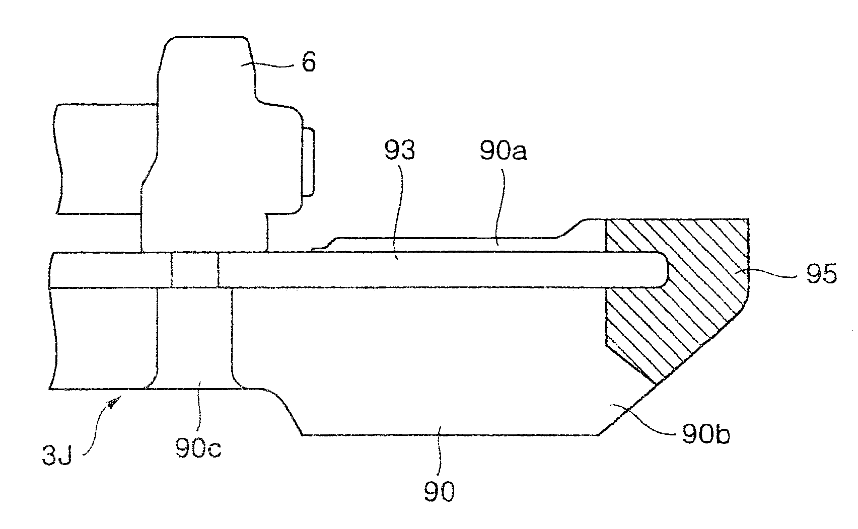
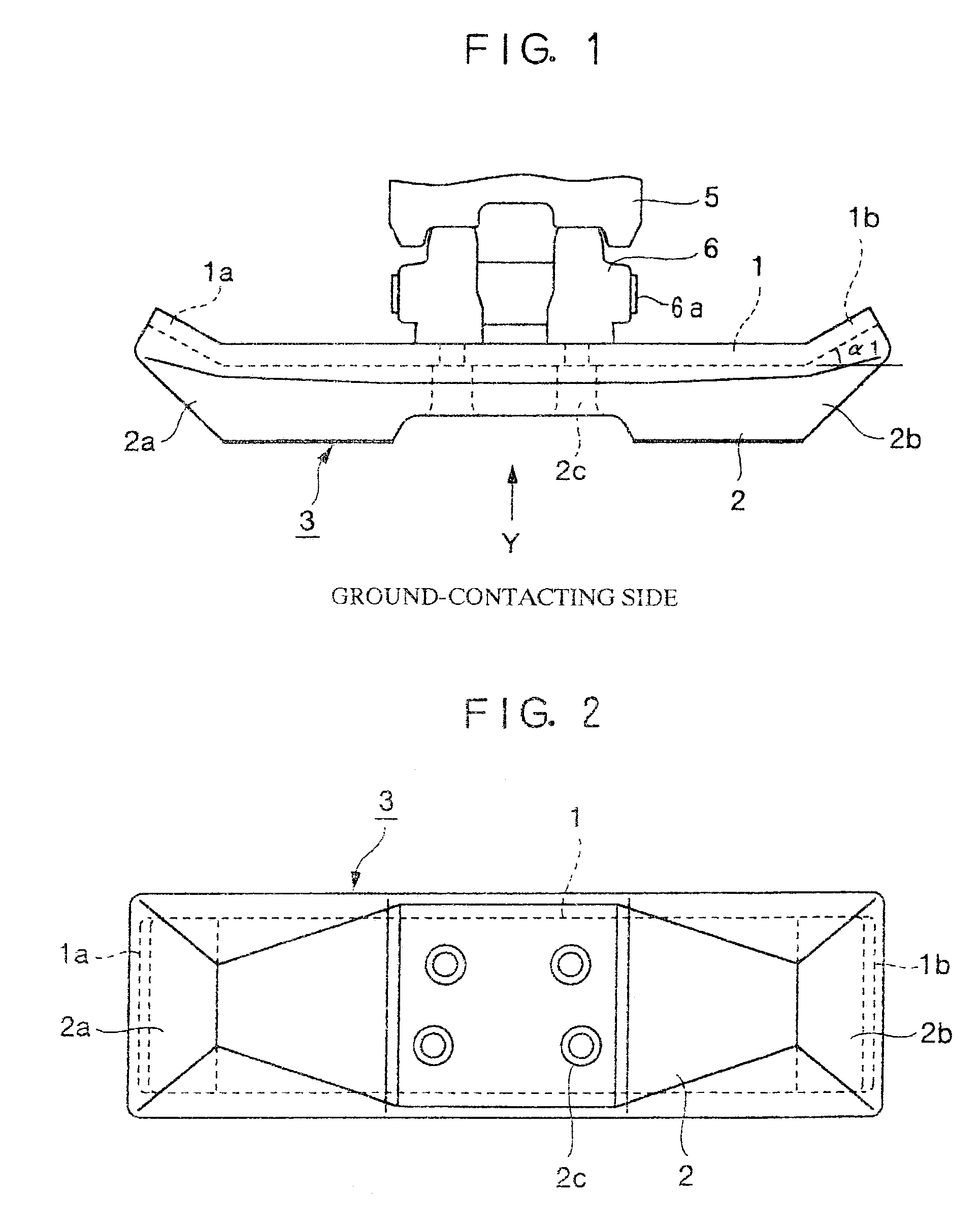
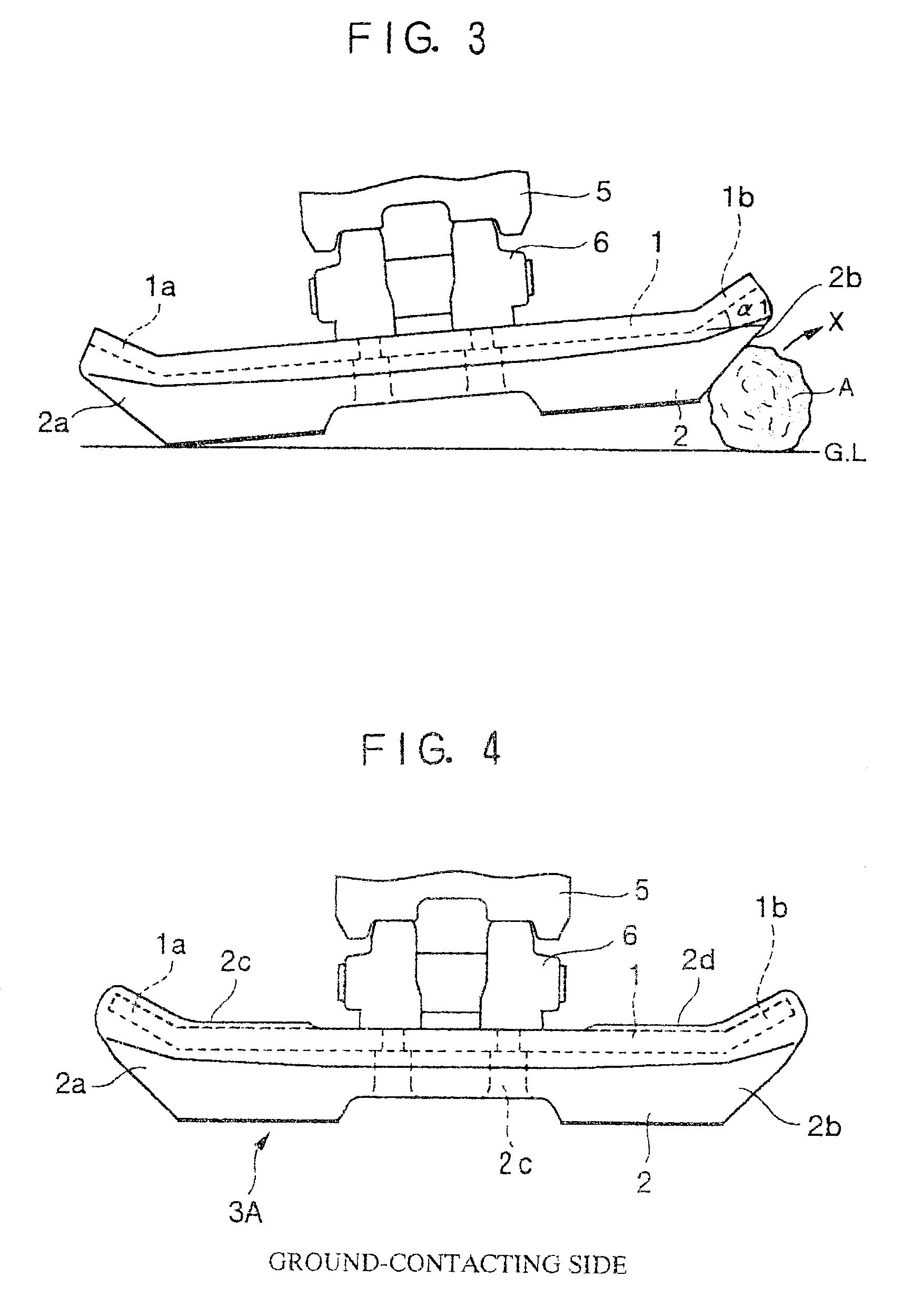
[0107]An elastic flat tread according to the present invention will be explained below with reference to FIG. 1 through FIG. 52. Initially, the elastic flat tread will be explained with reference to FIG. 1 through FIG. 4.
[0108]As FIG. 1 and FIG. 2 show, a core 1 is covered with and bonded to an elastic solid 2 such as rubber. A tread which is formed by the core 1 covered with and bonded to the elastic solid 2 is called an elastic flat tread 3. Bolts not illustrated are inserted into bolt insertion holes 2c provided in the elastic solid 2, thereby attaching the elastic flat tread 3 to a link 6. A number of elastic flat treads 3 are disposed in a traveling direction of a crawler, and end portions of the links 6 adjacent to each other are connected to each other with pins 6a to form an endless crawler belt. A lower roller 5 attached to a vehicle body not illustrated abuts to the tread surface of the link 6 to thereby rotate. The weight of the vehicle body is exerted on the core 1 via t...
second embodiment
[0113]Subsequently, the elastic flat tread will be explained with reference to FIG. 5 through FIG. 8.
[0114]As FIG. 5 and FIG. 6 show, a core 10 is covered with and bonded to an elastic solid 20 such as rubber. A tread which is formed by the core 10 covered with and bonded to the elastic solid 20 is called an elastic flat tread 3B. Bolts not illustrated are inserted into bolt insertion holes 20c provided in the elastic solid 20 to thereby attach the elastic flat tread 3B to the link 6. A number of elastic flat treads 3B are disposed in a traveling direction of a crawler, and end portions of the links 6 adjacent to each other are connected to each other with pins 6a to thereby form an endless crawler belt. The lower roller 5 attached to the vehicle body not illustrated abuts to the tread surface of the link 6 to thereby rotate. The weight of the vehicle body is exerted on the core 10 via the lower roller 5 and the link 6. Consequently, the core 10 is made of a material with high rigid...
third embodiment
[0123]Subsequently, the elastic flat tread will be explained with reference to FIG. 17 through FIG. 24.
[0124]As FIG. 17 and FIG. 18 show, in the elastic flat tread 33, a core 11 other than a link mounting surface 6b is covered with and bonded to an elastic solid 22 such as rubber. Only one side of the elastic flat tread 33 is illustrated, and the other side is omitted, since the other side is in a form symmetrical with the one side. In the elastic flat tread 33, the link 6 (See FIG. 1) is attached on the link mounting surface 6b with bolts being inserted into bolt insertion holes 22c provided in the elastic solid 22. As in the first embodiment, the elastic flat treads 33 form an endless crawler belt.
[0125]The core 11 is made of a material with high rigidity so as not to be deformed, and the end portion 11a is bent toward the side not in contact with the ground at a predetermined angle of bend α. The core end portion 11a is formed in such a shape that tapers toward a tip end 11c in a...
PUM
 Abstract
Description
Claims
Application Information
 - R&D
- Intellectual Property
- Life Sciences
- Materials
- Tech Scout
- Unparalleled Data Quality
- Higher Quality Content
- 60% Fewer Hallucinations
Browse by: Latest US Patents, China's latest patents, Technical Efficacy Thesaurus, Application Domain, Technology Topic, Popular Technical Reports.
© 2025 PatSnap. All rights reserved.Legal|Privacy policy|Modern Slavery Act Transparency Statement|Sitemap|About US| Contact US: help@patsnap.com


