
Refrigerator and control method thereof

a technology of refrigerator and control method, which is applied in the field of refrigerators, can solve the problems of inability to reduce the temperature of the refrigerating and freezing chamber simultaneously, and the efficiency of the cooling of the freezing chamber proportional to the supply of electricity, so as to reduce the power consumption rate

Active Publication Date: 2006-03-07
SAMSUNG ELECTRONICS CO LTD
View PDF5 Cites 11 Cited by
  • Summary
  • Abstract
  • Description
  • Claims
  • Application Information

AI Technical Summary

Benefits of technology

The present invention provides a refrigerator with improved energy efficiency by controlling the air blast fans in the storage chambers and the compressor. The control method involves determining if the air blast devices and the compressor are in starting conditions, and then turning on the air blast devices and the compressor sequentially or simultaneously after a designated time has passed. This reduces power consumption and improves the refrigerator's performance.

Problems solved by technology

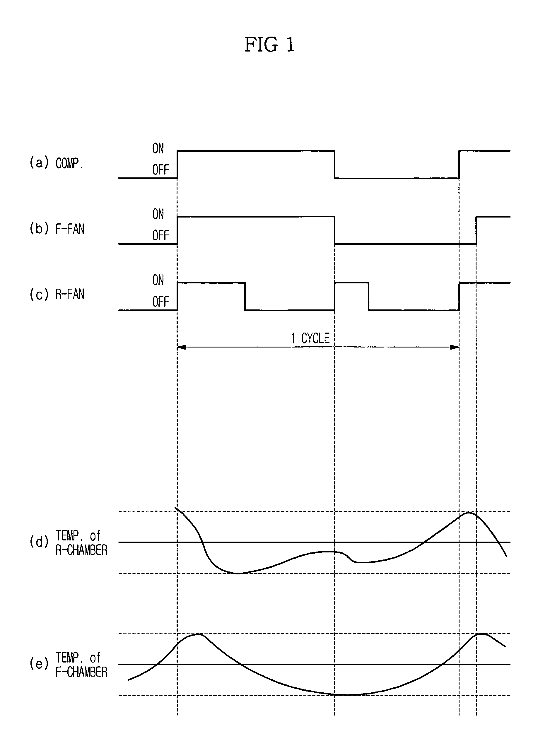
However, since the freezing chamber fan of the conventional refrigerator is continuously turned on even when the temperature of the freezing chamber does not decrease for a designated time from the starting of the compressor, the freezing chamber is not efficiently cooled in proportion to supplied electricity.
The above problem may be generated when an external temperature exceeds the load of the compressor and the temperatures of the refrigerating and freezing chambers cannot be simultaneously decreased even by the maximum operating capacity of the compressor.
Further, the above problem may be generated in a cooling system, in which the refrigerating chamber heat exchanger and the freezing chamber heat exchanger are connected in series and a refrigerant compressed by the compressor passes through a condenser and then passes through the refrigerating chamber heat exchanger and the freezing chamber heat exchanger sequentially.

Method used


Image

  • Refrigerator and control method thereof
  • Refrigerator and control method thereof
  • Refrigerator and control method thereof

Examples


Embodiment Construction

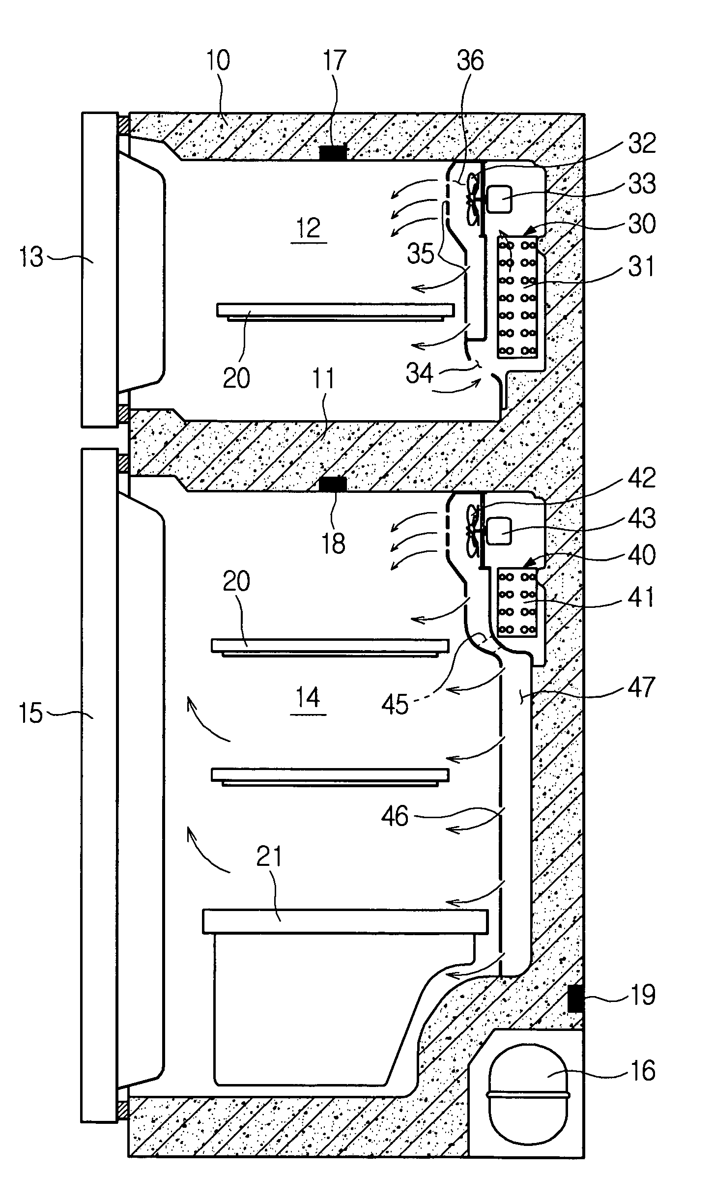
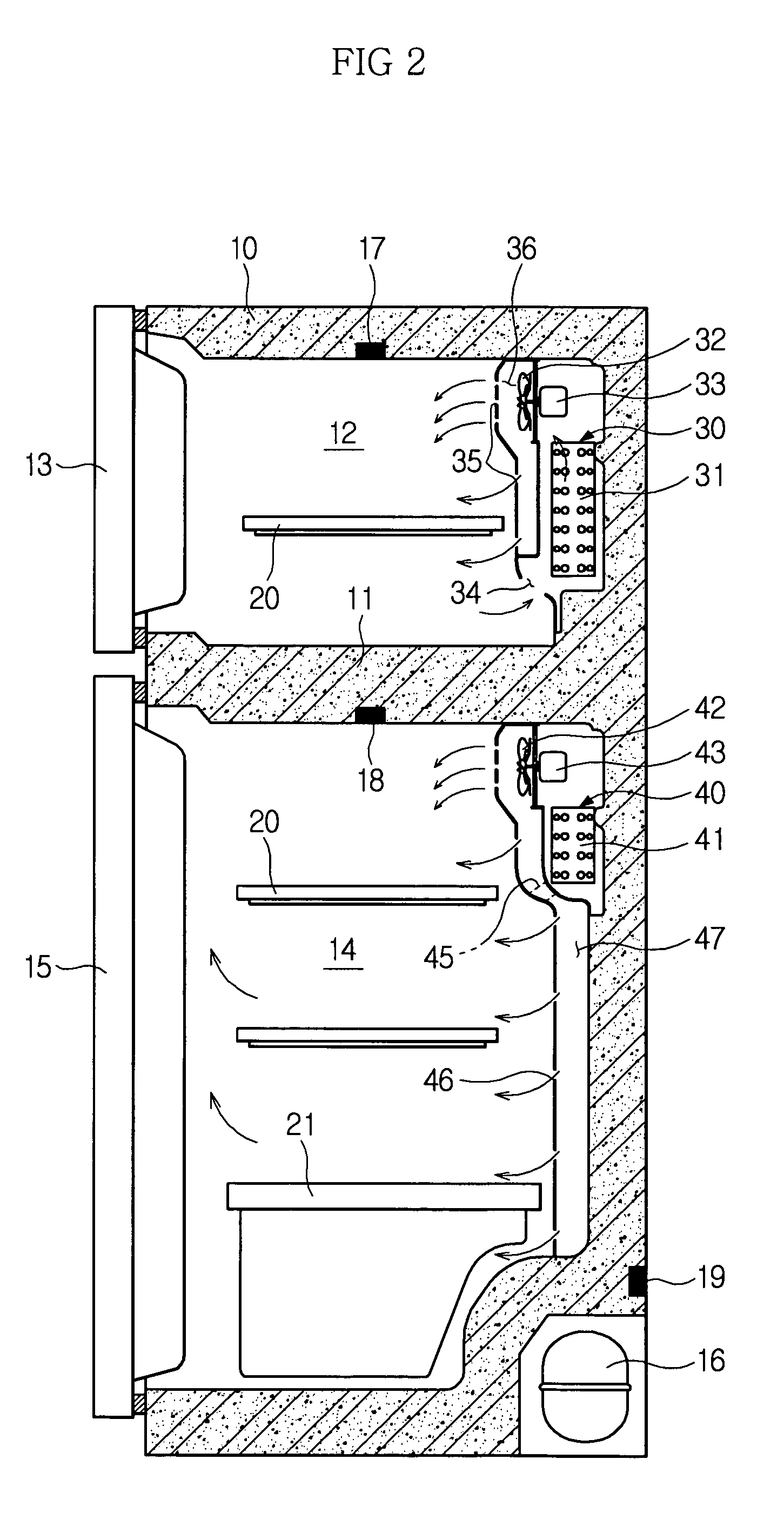
[0032]Now, a preferred embodiment of the present invention will be described in detail with reference to the annexed drawings.

[0033]As shown in FIG. 2, a refrigerator in accordance with an embodiment of the present invention comprises a main body 10, a freezing chamber 12 provided with an opened front surface and positioned at an upper part of the main body 10 divided by an intermediate partition 11, a freezing chamber door 13 for opening and closing the opened front surface of the freezing chamber 12, a refrigerating chamber 14 provided with an opened front surface and positioned at a lower part of the main body 10 divided by the intermediate partition 11, a refrigerating chamber door 15 for opening and closing the opened front surface of the refrigerating chamber 14, and a compressor 16 installed at a lower portion of a rear surface of the main body 10.

[0034]Freezing and refrigerating chamber heat exchanging units 30 and 40 for achieving the heat-exchange are respectively installe...


PUM


Abstract

A refrigerator, in which air blast fans in storage chambers are controlled so as to reduce a power consumption rate, and a control method of the refrigerator. The control method includes the steps of (a) determining whether or not a plurality of air blast devices, respectively connected to a plurality of storage chambers, and a compressor are respectively in starting conditions; (b) in case that it is determined that at least two air blast devices and the compressor are in the starting conditions, turning a part of the at least two air blast devices in the starting condition and the compressor on; and (c) turning all of the air blast devices in the starting condition on after a designated time from the turning-on of the air blast device elapses.

Description

CROSS-REFERENCE TO RELATED APPLICATION[0001]This application claims the benefit of Korean Patent Application No. 2004-21495, filed Mar. 30, 2004, in the Korean Intellectual Property Office, the disclosure of which is incorporated herein by reference.BACKGROUND OF THE INVENTION[0002]1. Field of the Invention[0003]The present invention relates to a refrigerator and a control method thereof, and, more particularly, to a refrigerator, in which air blast fans in storage chambers are controlled so as to reduce a power consumption rate, and a control method of the refrigerator.[0004]2. Description of the Related Art[0005]Generally, a refrigerator comprises refrigerating and freezing chambers for respectively storing foods in cold and frozen states, refrigerating and freezing chamber heat exchangers for cooling air in the refrigerating and freezing chambers by heat-exchanging, refrigerating and freezing chamber fans installed adjacent to the refrigerating and freezing chamber heat exchanger...

Claims


Application Information

Patent Timeline
Patent Type & Authority Patents(United States)
IPC IPC(8): F25D17/06F25B41/00F25D11/02F25D29/00G05D23/32
CPCF25D11/022F25D29/00F25B2600/112F25B2600/23Y02B40/32F25D2700/12F25D2700/122F25D2700/14Y02B30/743F25D2317/0682Y02B30/70Y02B40/00E02D5/20E02D11/00E02D2200/13E02D2250/0023E02D2600/20
Inventor JEONG, SEONG WOOKKIM, JUNG YEOB
Owner SAMSUNG ELECTRONICS CO LTD
Learn More