
Apparatus and method for deployment of an endoluminal device

a technology of endoluminal devices and iliac termini, which is applied in the field of endoluminal devices, can solve the problems of preventing successful medical treatment, difficult to ensure accurate placement of the iliac terminus of the second stent component, and ineffective stents,

Inactive Publication Date: 2006-02-28
LIFESHIELD SCI
View PDF38 Cites 212 Cited by
  • Summary
  • Abstract
  • Description
  • Claims
  • Application Information

AI Technical Summary

Problems solved by technology

Improper stent placement can prevent successful medical treatment.
It is difficult, however, to ensure accurate placement of the iliac terminus of the second stent component.
If the terminus is not placed far enough into the iliac, then the stent may be ineffective.
If the terminus extends too far, it may interfere with blood flow in arteries branching from the iliac, such as the internal iliac artery.
This problem also occurs in the deployment of multipart stents in other branched arteries.

Method used


Image

  • Apparatus and method for deployment of an endoluminal device
  • Apparatus and method for deployment of an endoluminal device
  • Apparatus and method for deployment of an endoluminal device

Examples


Embodiment Construction

[0020]The invention will next be illustrated with reference to the figures wherein the same numbers indicate similar elements in all figures. Such figures are intended to be illustrative rather than limiting and are included herewith to facilitate the explanation of the apparatus of the present invention.

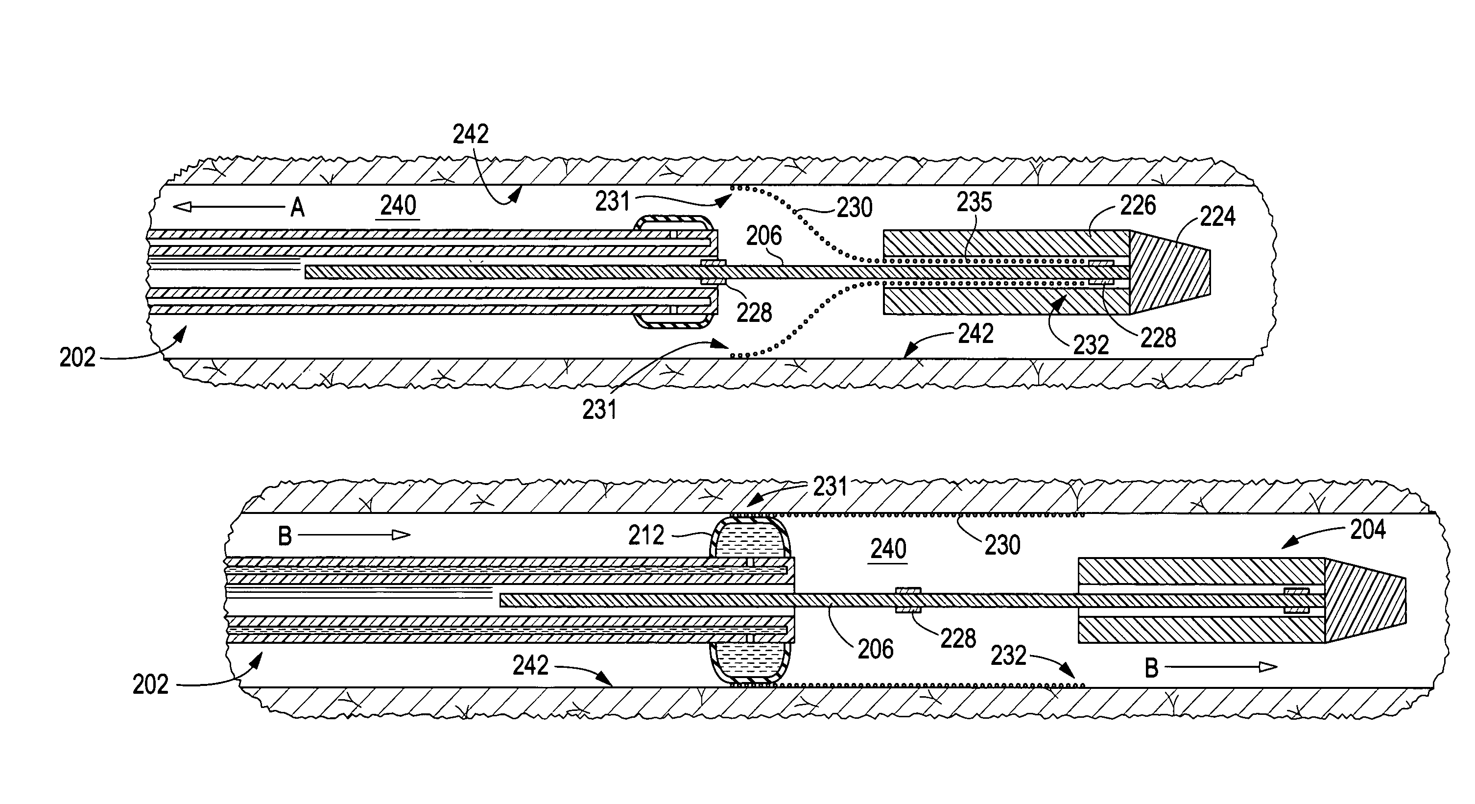
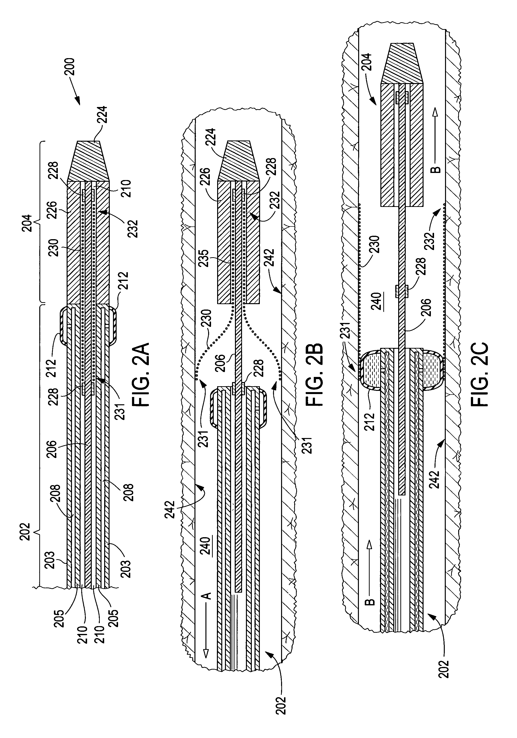
[0021]Referring now to FIGS. 2A–C there is shown an exemplary introducer embodiment 200 in accordance with the present invention. Retrograde portion 202 of introducer 200 comprises bitumen tubing having an exterior wall 203, an interior wall 205, an annular lumen 208 defined by the space between the interior wall and the exterior wall, and a central lumen 210 radially inward of the interior wall. Balloon 212 is located at or near the distal end of exterior wall in fluid communication with annular lumen 208, allowing fluid to flow through the annular lumen to inflate the balloon when desired. Anterograde portion 204 of introducer 200 is attached to shaft 206 and comprises distal tip ...


PUM


Abstract

An introducer deploys an endoluminal device in a distal location from a proximal location. The introducer comprises a retrograde portion, an anterograde portion axially moveable relative to the retrograde portion, a shaft having a distal tip and an anterograde sheath attached to the distal tip, and an inflatable balloon mounted radially outside the retrograde portion for anchoring the device during deployment from its proximal end to its distal end. The retrograde portion may comprise bilumen tubing having an external wall, an internal wall that defines a central lumen radially inward of the internal wall, and an annular lumen in fluid communication with the balloon defined between the external wall and the internal wall.

Description

TECHNICAL FIELD[0001]This invention relates generally to endoluminal devices and, more specifically, to methods and apparatus for deploying endoluminal devices in body lumens.BACKGROUND OF THE INVENTION[0002]A stent is an elongated device used to support an intraluminal wall. In the case of a stenosis, a stent provides an unobstructed conduit through a body lumen in the area of the stenosis. Such a stent may also have a prosthetic graft layer of fabric or covering lining the inside and / or outside thereof. Such a covered stent is commonly referred to in the art as an intraluminal prosthesis, an endoluminal or endovascular graft (EVG), or a stent-graft. A stent-graft may be used, for example, to treat a vascular aneurysm by removing the pressure on a weakened part of an artery so as to reduce the risk of rupture. Other devices, such as filters, particularly vena cava filters, may have similar structures to stents and may be placed in a body lumen by similar methods. As used herein, th...

Claims


Application Information

Patent Timeline
Patent Type & Authority Patents(United States)
IPC IPC(8): A61F2/06A61F11/00A61F2/84
CPCA61F2/958
Inventor THOMPSON, RICHARDJOHNSON, WADE
Owner LIFESHIELD SCI
Learn More