Device and method for aligning disk-shaped substrates

a technology of disk-shaped substrates and devices, applied in the direction of manipulators, electrical equipment, conveying parts, etc., to achieve the effect of eliminating cost and problems associated with suction devices and easy integration

Inactive Publication Date: 2006-02-28
STEAG RTP SYST
View PDF7 Cites 16 Cited by
  • Summary
  • Abstract
  • Description
  • Claims
  • Application Information

AI Technical Summary

Benefits of technology

[0012]Pursuant to the invention, this object is realized with an apparatus of the aforementioned type by means of at least one movable first support, which forms a support plane, for receiving the substrate, a device for tilting the first support relative to the horizontal in order to bring the support plane into an inclined position relative to the horizontal, an abutment against which the substrate is movable due to the incline, and a rotation device for rotating the substrate. The movable first support enables a depositing and a removal of the substrate in an essentially horizontal position as a result of which the apparatus can be easily integrated into existing systems in which handling devices generally hold the substrates in horizontal positions. It is therefore not necessary to alter the previously used handling devices. Due to the inclined support, the substrate is automatically moved into a spatially fixed position against the abutment. Due to the rotation device, the substrate can now be moved into a prescribed rotated position, which is detected by the alignment detection unit. The positioning and alignment are effected in a single step and require no complicated control of various elements. Therefore, a suctioning of the substrate is not required, since a lateral sliding during the rotation is not possible due to the inclined position and the abutment. As a result, the cost and problems associated with the suction device are eliminated.

Problems solved by technology

Therefore, a suctioning of the substrate is not required, since a lateral sliding during the rotation is not possible due to the inclined position and the abutment.

Method used


Image

  • Device and method for aligning disk-shaped substrates
  • Device and method for aligning disk-shaped substrates
  • Device and method for aligning disk-shaped substrates

Examples


Embodiment Construction

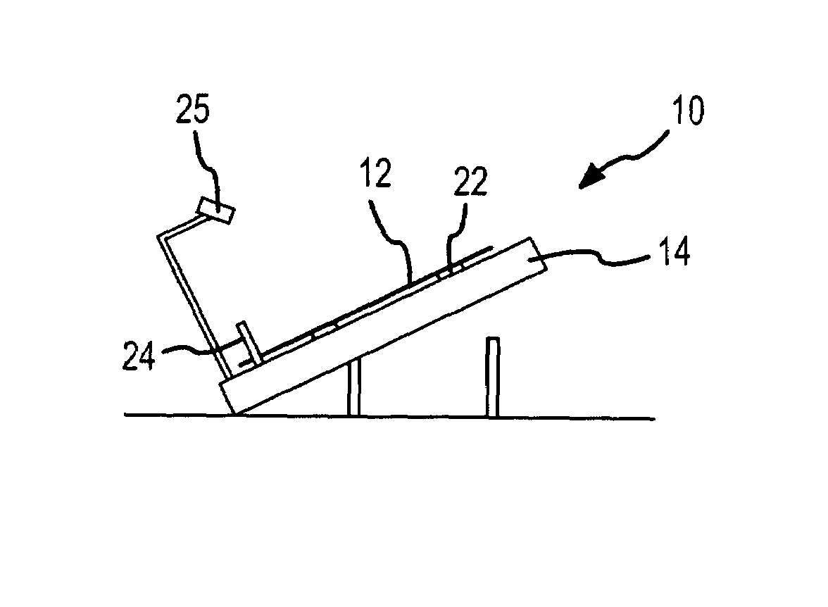
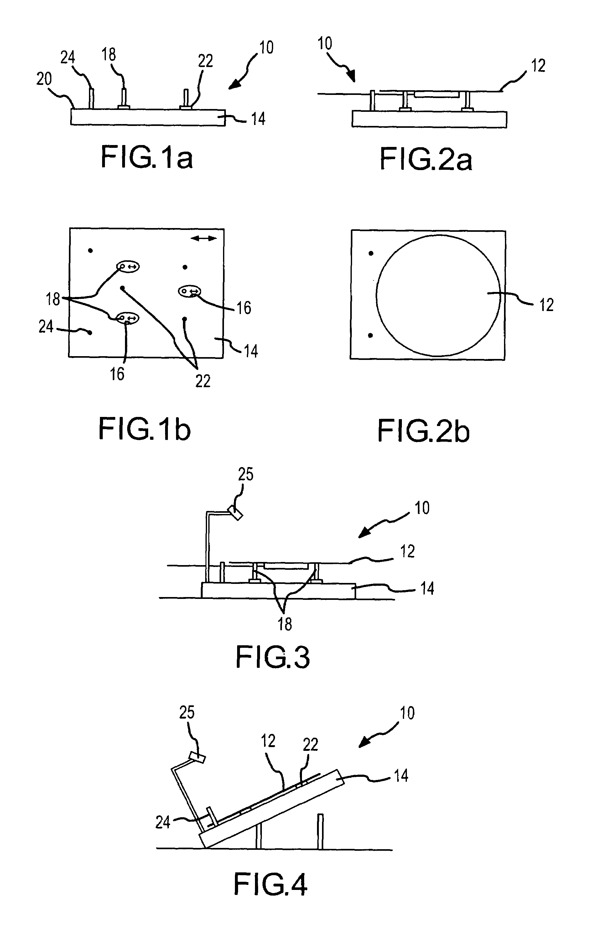
[0045]FIGS. 1a and 1b show a schematic side view and a top view respectively of an apparatus 10 for the alignment of disk-shaped semiconductor wafers 12 (see FIG. 2). The apparatus 10 has a plate 14 which, as will be described subsequently, can be tilted. The plate 14 has three oval openings 16 that extend upwardly from below through the plate 14. Three support pins 18 extend through the openings 16 in the plate 14 and are secured to a non-illustrated base plate. The support pins 18 form a three-point support having an essentially horizontal support plane for receiving the semiconductor wafer 12, as can be best seen in FIG. 2a. Disposed on an upper side 20 of the plate 14 are three Teflon disks 22 which, as will be described subsequently, serve as support elements for the semiconductor wafer 12 when the plate 14 is tilted relative to the horizontal. Instead of the three pins 18 and the three disks 22, it is also possible to respectively provide two elongated elements that form a sup...


PUM


Abstract

The invention relates to a simple and cost-effective method for aligning substrates. In order to achieve this, the invention provides a device for aligning disc-shaped substrates, in particular semiconductor wafers, comprising an alignment detection unit, at least one first support for receiving the substrate, which forms an oblique plane in relation to the horizontal, a stop against which the substrate can be displaced as a result of the oblique angle and a rotational device for rotating the substrate. The invention also relates to a method for aligning disc-shaped substrates, in particular semiconductor wafers, comprising the following steps: displacement of the substrate into an oblique position in relation to the horizontal, in which the substrate is held on a support which forms a tilted plane in relation to the horizontal and lies against a stop as a result of the oblique angle; rotation of the substrate into a predefined rotational position; and monitoring of the rotational position using a detection unit.

Description

BACKGROUND OF THE INVENTION[0001]The present invention relates to an apparatus and a method for the alignment of disk-shaped substrates, especially semiconductor wafers, and includes an alignment detection unit.[0002]In the semiconductor industry, to manufacture semiconductor elements generally semiconductor disks, also known as wafers, that are comprised of a single crystal, are subjected to various treatment processes. These treatment processes are greatly automated, and between the treatment processes the semiconductor disks are transported with handling devices, which are generally support plates. In this connection, a centered placement of the disks upon the support plates is important in order to ensure a proper positioning of the disks in the various treatment devices. In addition, the disks must be aligned in accordance with the axes of their crystal lattices. Both the centering as well as the alignment of the disks is undertaken by alignment apparatus, which are also design...

Claims


Application Information

Patent Timeline
Patent Type & Authority Patents(United States)
IPC IPC(8): B25J11/00H01L21/68
CPCH01L21/68Y10S414/136H01L21/68764
Inventor GRAF, OTTMARMANTZ, PAUL
Owner STEAG RTP SYST
Why Eureka
Try Eureka