
Tunable optical instruments

a technology of optical instruments and osas, applied in the field of tunable optical instruments, can solve the problems of bulky and expensive osas and ocms, slow system tuning, and low accuracy

Inactive Publication Date: 2006-02-21
II VI DELAWARE INC +1
View PDF39 Cites 131 Cited by
  • Summary
  • Abstract
  • Description
  • Claims
  • Application Information

AI Technical Summary

Benefits of technology

[0011]Packaging variants can be made. For example, the TTFF and the optical detector can be mounted in a single hermetic package. The single hermetic package may be a TO-style package. Within the single hermetic package may be one or more discrete temperature sensors. Also, within the single hermetic package may be one or more temperature-stabilizing devices.
[0012]Several calibration aids can be included. The optical instrument may further include an external source of one or more known wavelength signals. Alternatively, the instrument may include an internal source of one or more known wavelength signals. In yet another alternative, the instrument may further comprise passive interferometric structures within the optical instrument that create a stable wavelength reference. In this alternative, the interferometric structures may include a substrat

Problems solved by technology

Conventional OSAs and OCMs are bulky and expensive because the tunable filters used employ mechanical tuning means, such as moving a grating, stretching a fiber, etc.
Such systems are also slow to tune, often requiring seconds to tune just a few nanometers in wavelength.

Method used


Image

  • Tunable optical instruments
  • Tunable optical instruments
  • Tunable optical instruments

Examples


Embodiment Construction

[0055]The present invention will be better understood upon reading the following detailed description of various aspect of embodiments thereof in connection with the figures.

[0056]Tunable thin film filters (TTFFs) are free-space filters that admit beams of light, for example collimated light, and filter out specific wavelength or sets of wavelengths for transmission or reflection. The optical beams to be filtered are unguided except for input and output optics which extract them and insert them into waveguides such as optical fibers.

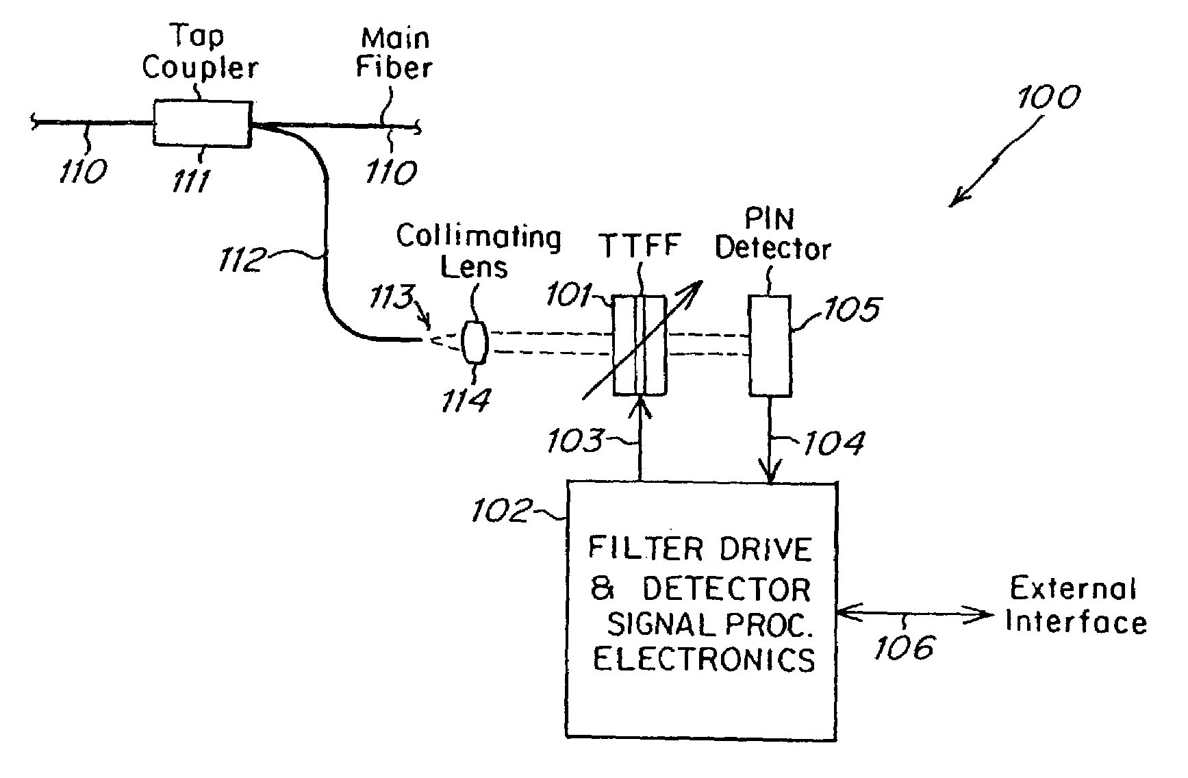
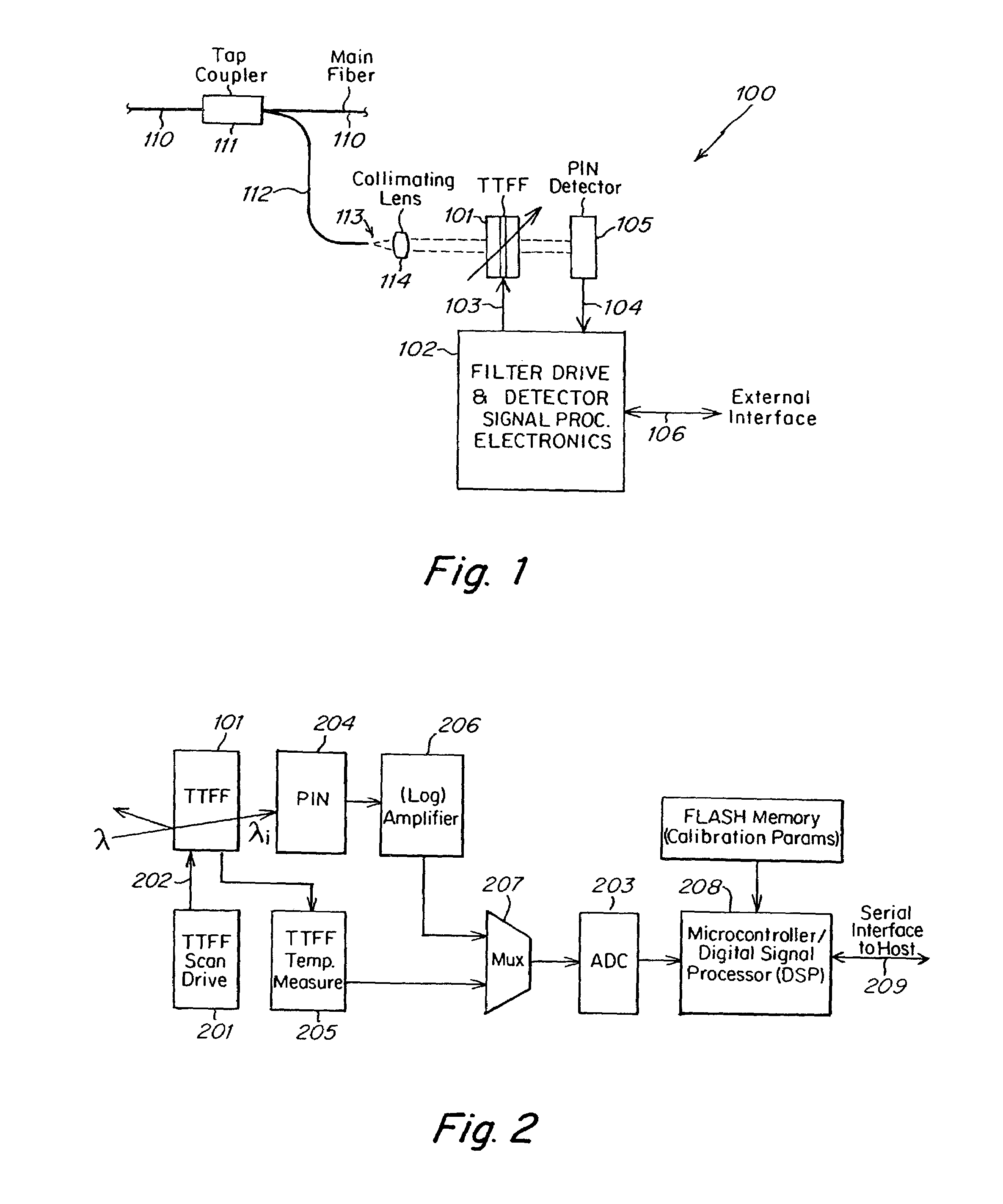
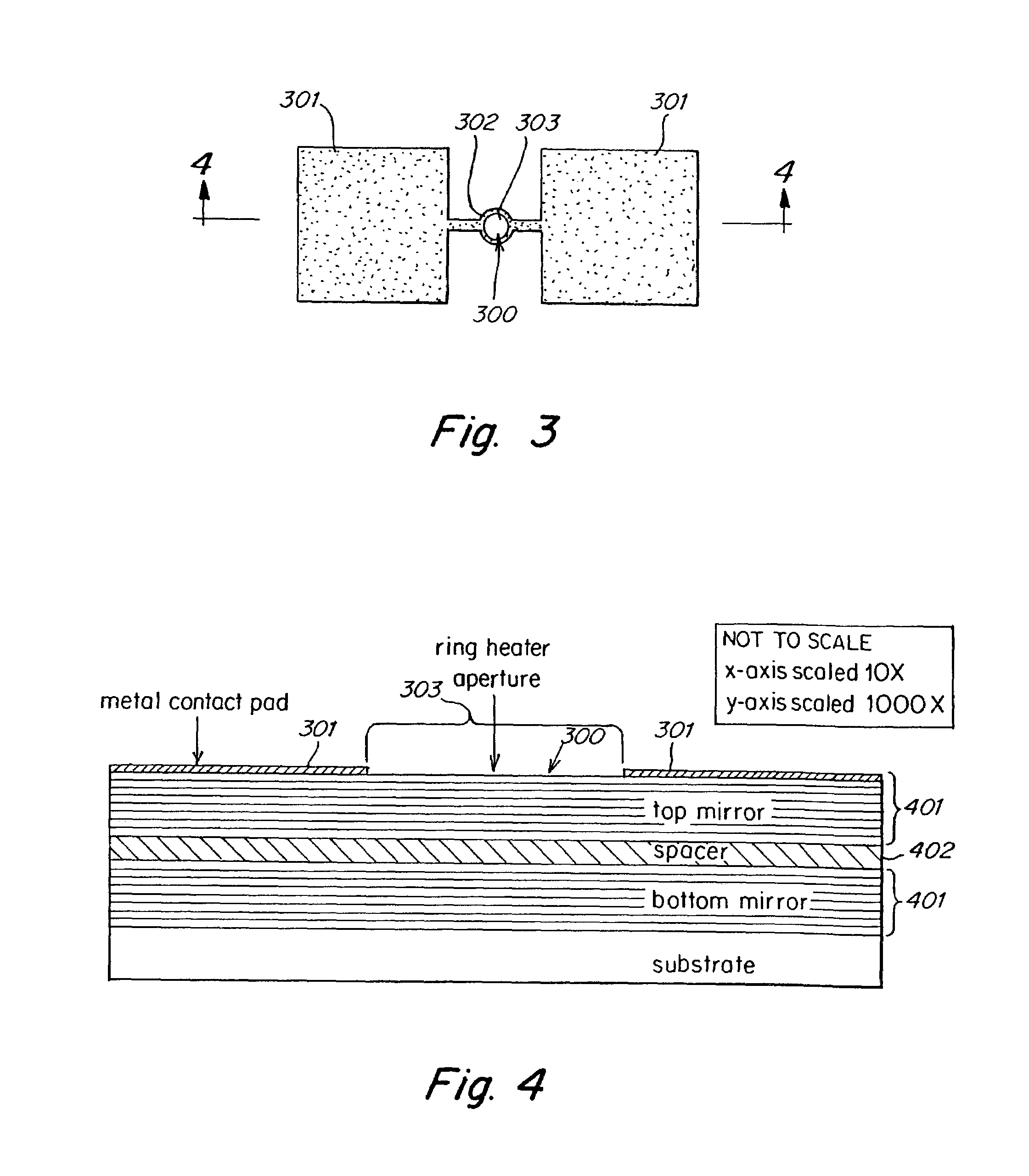
[0057]A block diagram of an optical instrument 100 including a TTFF 101, such as an OSA or OCM is shown in FIG. 1. The TTFF 101 comprises semiconductor thin films possessing large thermo-optic coefficients leading to wide tunability with no moving parts. Integral with or closely associated with the TTFF 101 are devices for heating and / or cooling the filter over a wide temperature range. A signal-carrying optical fiber 110 passes through a top coupler 111...


PUM


Abstract

An optical instrument including: a thermo-optically tunable, thin film, free-space interference filter having a tunable passband which functions as a wavelength selector, the filter including a sequence of alternating layers of amorphous silicon and a dielectric material deposited one on top of the other and forming a Fabry-Perot cavity structure having: a first multi-layer thin film interference structure forming a first mirror; a thin-film spacer layer deposited on top of the first multi-layer interference structure, the thin-film spacer layer made of amorphous silicon; and a second multi-layer thin film interference structure deposited on top of the thin-film spacer layer and forming a second mirror; a lens for coupling an optical beam into the filter; an optical detector for receiving the optical beam after the optical beam has interacted with the interference filter; and circuitry for heating the thermo-optically tunable interference filter to control a location of the passband.

Description

RELATED APPLICATIONS[0001]This application claims domestic priority under 35 U.S.C. §119(e) to provisional U.S. patent applications having Ser. Nos. 60 / 309,704 (filed Aug. 2, 2001), 60 / 310,047 (filed Aug. 4, 2001), 60 / 322,208 (filed Sep. 14, 2001), 60 / 335,178 (filed Nov. 28, 2001), 60 / 386,973 (filed Jun. 6, 2002); and 60 / 394,500 (filed Jul. 9, 2002), all incorporated herein by reference.BACKGROUND OF THE INVENTION[0002]Tunable optical instruments are a class of instruments in which a property of light, such as power level, is measured at more than one wavelength. Such instruments include optical spectrum analyzers (OSAs), optical channel monitors (OCMs) and others used in the wavelength division multiplexed (WDM) optical communication field, as well as other fields.[0003]An OSA is a piece of equipment or a measurement instrument that receives an optical input and produces an output that represents the optical power contained in the optical input over a range of wavelengths. When we ...

Claims


Application Information

Patent Timeline
IPC IPC(8): G01B9/02G02B5/02G01N21/25G02B5/28G02B6/34G02B6/42G02F1/01G02F1/21
CPCG01J3/0286G02B6/29358G02B6/29361G02B6/29367G02B6/29395G02B6/4204G02B6/4206G02B6/4214G02B6/4225G02B6/4246G02B6/4249G02F1/0147G02F1/218G01J3/26G02B6/29311G01N21/251G02B6/29398G02B6/4224G02F1/0121G02F2001/213G02F2202/103G02F2202/104G02F2203/055G02B6/4215G02B6/4251G02B6/4263G02B6/4266G02B6/4286G02F1/213
Inventor DOMASH, LAWRENCE H.PAYNE, ADAM M.MA, EUGENE Y.NEMCHUK, NIKOLAYWU, MINGMURANO, ROBERTSHERMAN, STEVENWAGNER, MATTHIAS
Owner II VI DELAWARE INC
Learn More