
System and method for warning an operator of a vehicle if the vehicle is operating in a condition that may result in drive belt failure

a technology for warning operators and vehicles, applied in mechanical equipment, transportation and packaging, and machining details, etc., can solve problems such as belt failure, belt burns, warps or fraying, and belt failure,

Inactive Publication Date: 2006-02-21
POLARIS IND INC
View PDF10 Cites 53 Cited by
  • Summary
  • Abstract
  • Description
  • Claims
  • Application Information

AI Technical Summary

Benefits of technology

The invention provides a system for warning an operator of a vehicle if they are operating in a condition that may result in drive belt failure. The system includes sensors to determine engine speed and ground speed, and a processor to compare these data with transmission gear placement. If the engine speed is too high for a given ground speed and transmission gear placement, a warning signal is generated to alert the operator. This system can help prevent damage to the drive belt and improve operational efficiency of the vehicle.

Problems solved by technology

This friction creates a significant amount of heat.
If this heat is not adequately removed from the sheaves, the belt can become quite hot and, under extreme conditions, the belt will burn, warp or fray and thereby fail or operate improperly.
Drive belts are more apt to fail under certain vehicle operating conditions.
This conditions can occur when an operator applies full throttle even though the wheels on the vehicle are stuck or when the vehicle is towing a very heavy load.
The increased throttle results in rotation of the drive clutch but the stuck wheels or the heavy load prevents rotation of the driven clutch.
The drive belt absorbs the large difference in speeds by sliding relative to the stationary clutch which generates significant amount of heat that may result in belt failure.
Another scenario in which the drive belt is more apt to fail is if the vehicle is driven in the wrong gear.
If the vehicle is mistakenly operated in High gear when conditions warrant Low gear operation, the load on the engine and on the CVT drive clutch increases.
This increased load causes the drive belt to slip on the driven clutch resulting in extreme heat generation.

Method used


Image

  • System and method for warning an operator of a vehicle if the vehicle is operating in a condition that may result in drive belt failure
  • System and method for warning an operator of a vehicle if the vehicle is operating in a condition that may result in drive belt failure
  • System and method for warning an operator of a vehicle if the vehicle is operating in a condition that may result in drive belt failure

Examples


Embodiment Construction

[0017]FIG. 1 is a perspective view of an ATV according to a preferred embodiment of the present invention. An ATV 10 has a chassis 12 upon which is mounted an engine (not shown), a transmission system (not shown) including front and rear axles, and wheels 22. The ATV has a front and rear rack 24, 26 for carrying loads. An instrument cluster (see FIG. 6) is located on the chassis 12 where it can be viewed by the operator of the vehicle while operating the vehicle. While the invention is described with reference to an ATV, the invention is not so limited and can be used with snowmobiles or other vehicles that utilize CVTs.

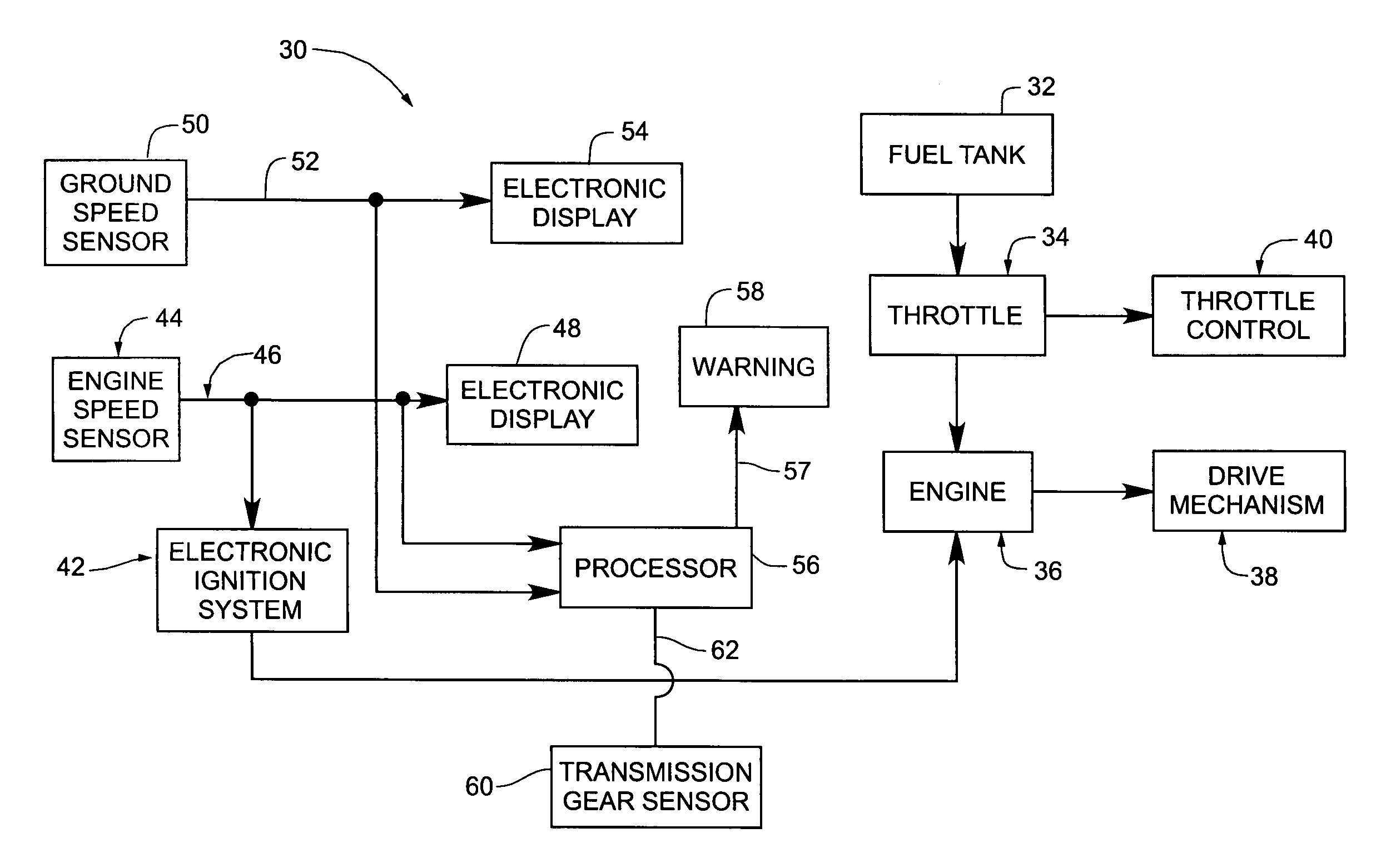
[0018]FIG. 2 is a block diagram of a portion of an engine configuration 30 incorporating a warning system according to a preferred embodiment of the present invention. A fuel tank 32 is coupled to provide fuel to an engine 36 via a throttle 34. The engine 36 converts the fuel into power to drive the vehicle drive mechanism 38. The amount of power provided to the driv...


PUM


Abstract

A system and method for warning an operator of a vehicle if the vehicle is operating in a condition that may result in drive belt failure. The ground speed of the vehicle, its engine speed and transmission gear placement are compared to determine if the engine speed is too high for a given ground speed and transmission gear placement. If it is too high, a warning is generated to alert the operator if the vehicle that the drive belt is in danger of failing.

Description

BACKGROUND OF THE INVENTION[0001]Many All Terrain Vehicles (ATVs) and snowmobiles are equipped with belt-driven continuously variable transmissions. Continuously Variable Transmissions (CVTs) alleviate the need for the operator of the vehicle to shift the transmission as the vehicle accelerates through its range of speeds. As described in U.S. Pat. No. 6,176,796, CVTs are comprised of a drive clutch, a driven clutch, and drive belt, typically a V-belt, disposed about the clutches. The drive clutch is coupled to the engine drive shaft and the driven clutch is coupled to the vehicle's wheels on ATVs or endless track in the case of snowmobiles and is driven by the drive clutch though the drive belt. Each of the clutches are typically configured as a pair of opposed sheaves that rotate together about a common axis. Typically one sheave of each clutch is moveable axially while the other remains stationary. The movable sheaves thus move away from or towards the other sheave during operati...

Claims


Application Information

Patent Timeline
Patent Type & Authority Patents(United States)
IPC IPC(8): B60Q1/00
CPCF16H57/01F16H2059/465F16H2057/016
Inventor GUSTAFSON, GARY L.
Owner POLARIS IND INC
Learn More