
Systems and methods for automatic and continuous coating supply during optical fiber production

a technology of automatic and continuous coating supply and optical fiber, which is applied in the field of optical fiber, can solve problems such as adversely affecting the yield of optical fiber, and achieve the effect of increasing the amount of coating material and cost-effectiveness

Inactive Publication Date: 2006-02-21
FURAKAWA ELECTRIC NORTH AMERICA INC
View PDF8 Cites 6 Cited by
  • Summary
  • Abstract
  • Description
  • Claims
  • Application Information

AI Technical Summary

Benefits of technology

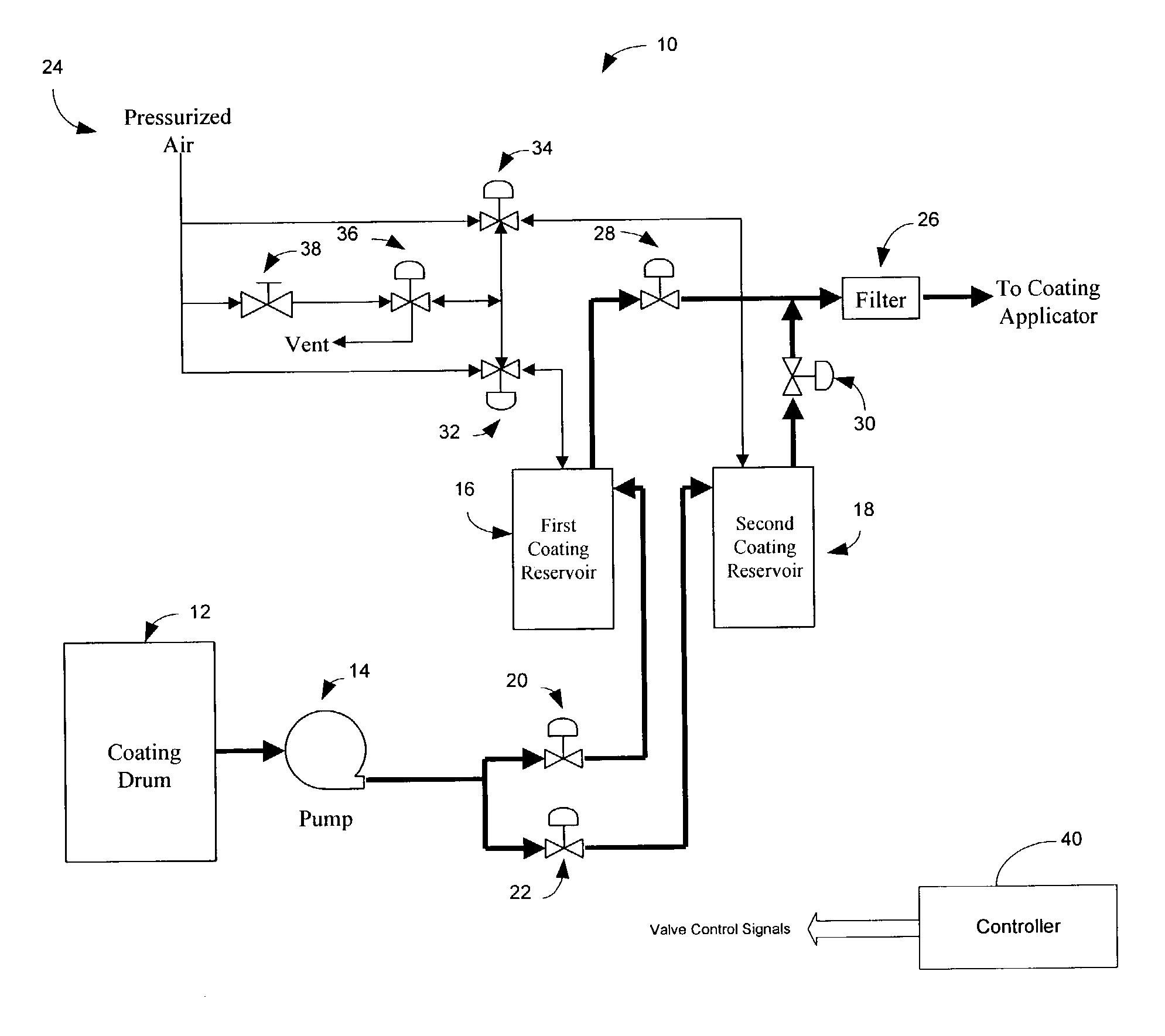
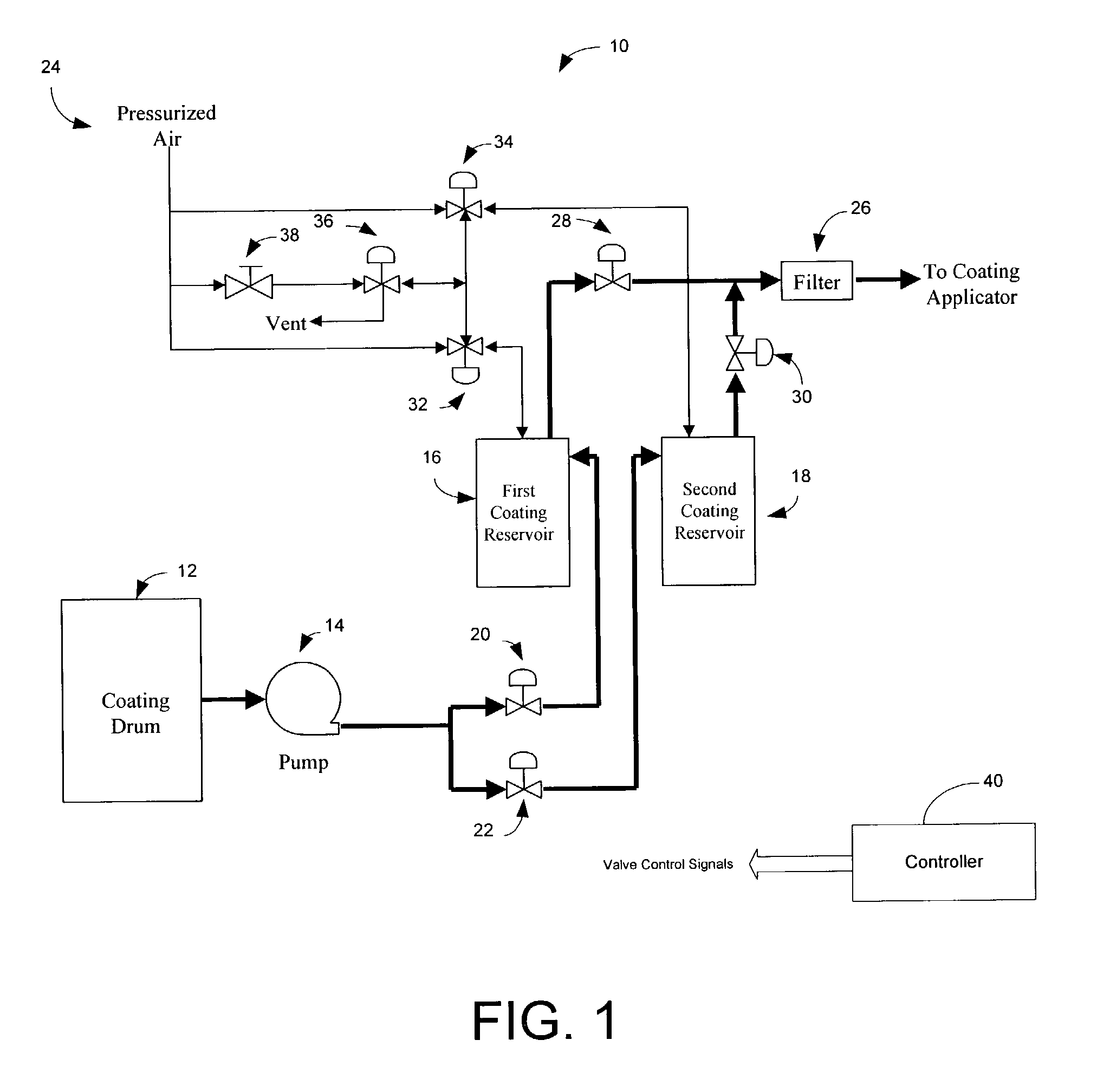
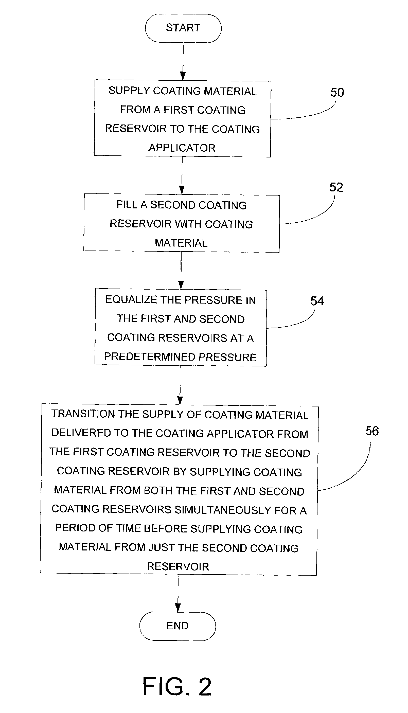
[0011]The present invention provides systems and methods for the automatic and continuous supply of coating material to the coating applicator. The present invention achieves this, at least in part, by switching from one coating reservoir to another by way of a transitional period in which both coating reservoirs are supplying coating material to the coating applicator. The coating reservoirs share a vent line(s), which is used to slowly pressurize the standby reservoir after it has been filled, thereby preventing the air pressure to the in-use coating reservoir from dropping an undesirable amount. Once pressurized, the standby coating reservoir can begin supplying coating material once the amount of coating material in the in-use coating reservoir drops below a predetermined level. During a transition period, both reservoirs supply coating material, which is possible because of the prior pressurization of the standby coating reservoir. After a short transition period, the empty coating reservoir stops supply coating material so that it can be refilled and off gassed.
[0012]By providing a continuous coating supply, the present invention advantageously removes a significant roadblock to reducing costs and increasing yields, that being the stopping of the fiber draw process to switch coating reservoirs. In addition, the present invention provides a cost effective solution requiring only minimal modifications to existing coating supply systems utilizing two reservoirs per coating.
[0015]In the above method, the steps of supplying the coating material, filling the second coating reservoir and transitioning the supply of coating material are controlled with at least a plurality of valves controlled by a computer processor-based controller. In addition, the step of supply coating material from the first coating reservoir may include applying air pressure from the air pressurized air source, and wherein equalizing the pressure in the first and second coating reservoirs includes slowly pressurizing the second coating reservoir with pressurized air from the pressurized air source so that the air pressure in the first coating reservoir does not fall out of a predetermined range.

Problems solved by technology

Preferably, the pressure is equalized without allowing the pressure in the first coating reservoir from dropping an amount that would adversely affect the optical fiber yield.

Method used


Image

  • Systems and methods for automatic and continuous coating supply during optical fiber production
  • Systems and methods for automatic and continuous coating supply during optical fiber production
  • Systems and methods for automatic and continuous coating supply during optical fiber production

Examples


Embodiment Construction

[0021]The present inventions now will be described more fully hereinafter with reference to the accompanying drawings, in which some, but not all embodiments of the invention are shown. Indeed, these inventions may be embodied in many different forms and should not be construed as limited to the embodiments set forth herein; rather, these embodiments are provided so that this disclosure will satisfy applicable legal requirements. Like numbers refer to like elements throughout.

[0022]The present invention is disclosed below in the context of a single coating system, though it will be appreciated by those skilled in the art that the present invention is equally applicable to dual coating systems which have two coating supply systems that are substantially identical (e.g., one for the primary coating and one for the secondary coating). Yet further, the present invention can be utilized in coating supply systems used in the fabrication of a fiber matrix, as well as any other coating supp...


PUM

PropertyMeasurementUnit
pressureaaaaaaaaaa
transmission propertiesaaaaaaaaaa
corrosiveaaaaaaaaaa

Abstract

Systems and methods are disclosed for an automatic and continuous supply of coating material to a coating applicator in optical fiber fabrication. The present invention switches from one coating reservoir to another by way of a transitional period in which both coating reservoirs are supplying coating material to the coating applicator. For example, while an in-use reservoir is supplying the coating material to the coating applicator, a standby reservoir is being filled, settled to off gas air bubbles and then slowly pressurized. A sized orifice is used to slowly bleed off pressure from the in-use reservoir at a rate that does not allow the pressure in the in-use reservoir from falling out of a desired pressure range. When the in-use reservoir is substantially emptied of coating material and the pressures in both reservoirs are substantially equalized, then both reservoirs simultaneously supply coating material to the coating applicator for a period of time before switching completely over to the standby reservoir.

Description

BACKGROUND OF THE INVENTION[0001]I. Field of the Invention[0002]The present invention relates generally to optical fiber, and more particularly to supplying coating material to a coating applicator in the fabrication of optical fiber.[0003]II. Description of Related Art[0004]Methods for the manufacture of optical fibers by drawing the fiber from a glass preform and coating the fiber with a liquid polymer immediately after drawing are well known. The polymer coating serves as a protective coating to prevent airborne particles from impinging upon and adhering to the surface of the drawn fiber, which would mechanically weaken the fiber or even affect its transmission properties. Also, the coating shields the fibers from surface abrasion, which could occur as a result of subsequent manufacturing processes and / or handling during installation. The coating also provides protection from corrosive environments and spaces the fibers in cable structures.[0005]Optical fibers are coated with the...

Claims


Application Information

Patent Timeline
Patent Type & Authority Patents(United States)
IPC IPC(8): B05C11/10G02B6/44C03C25/12C03C25/18G02B6/02
CPCC03C25/18B05C11/1002B05C11/101Y10T137/3127Y10T137/3124
Inventor HONG, SIU-PINGSHIROISHI, JASON W.HUDSON, JAMES A.
Owner FURAKAWA ELECTRIC NORTH AMERICA INC
Learn More