
Jointer clamp

Active Publication Date: 2006-02-21
GEN TOOLS & INSTR
View PDF10 Cites 22 Cited by
  • Summary
  • Abstract
  • Description
  • Claims
  • Application Information

AI Technical Summary

Benefits of technology

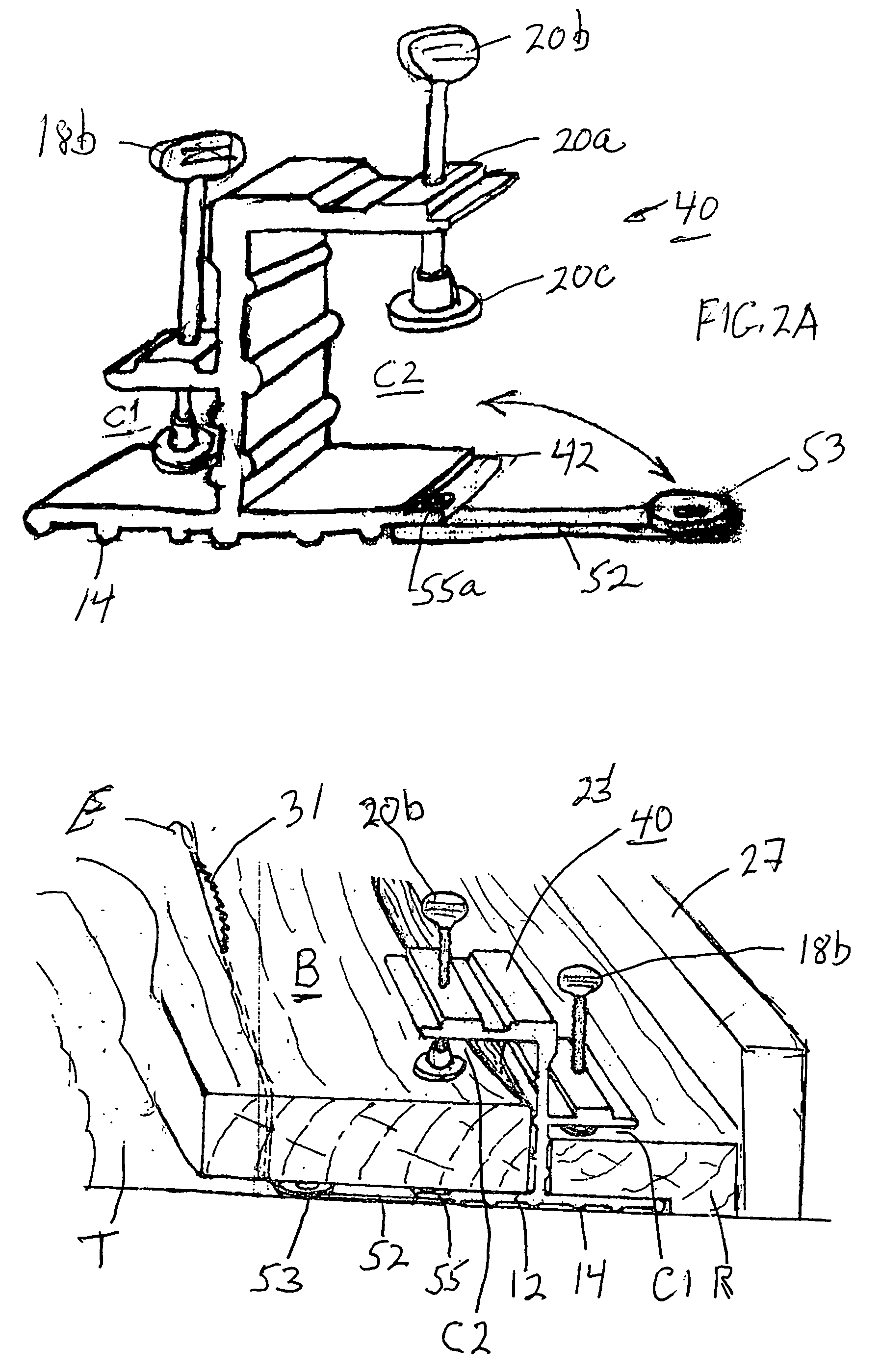
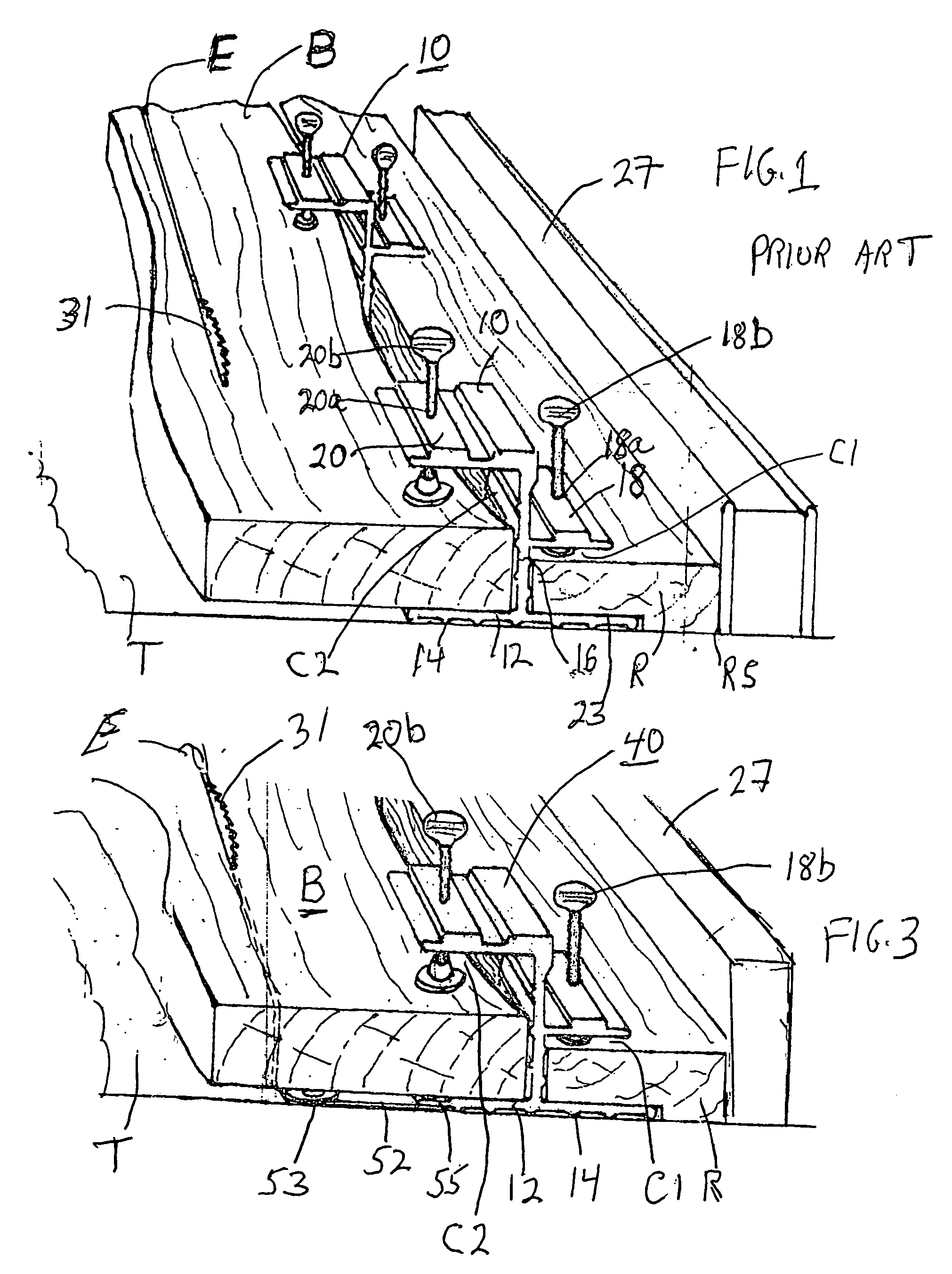
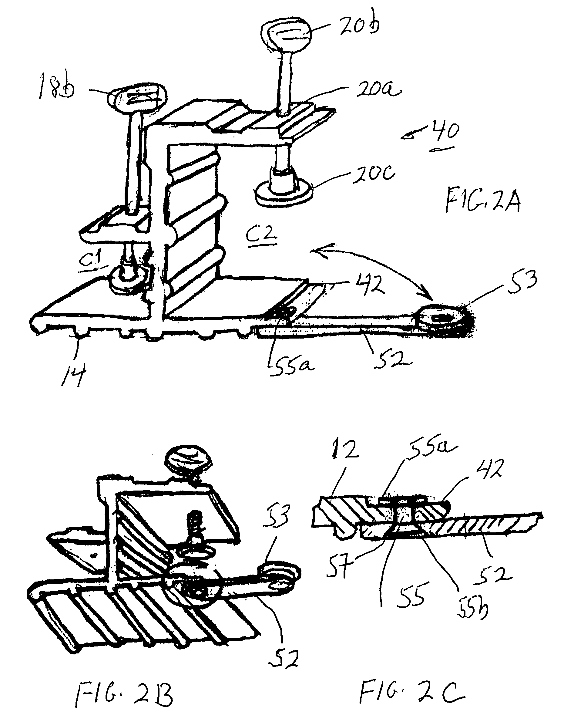
[0010]To enhance the support of the working board, one end of a shim arm is pivotally mounted at one end of the base part that forms the channel below the upper support wall in which one edge of the working board is placed. The shim arm extends along the outer edge of this base part and is of the same length as the base part edge. A shim support pad is mounted at the free end of the pivotal arm and its upper surface is in the same plane as the upper surface of the clamp base on which the working board is supported. The shim arm swings out from the base so that the shim support pad forms a support on which the lower surface of the working board rests. This effectively increases the width of the base part that forms the channel for the working board and provides a wider support for the working board outwardly of the clamp base. This prevents the working board from tilting as it is being pushed over the saw table into the rotating saw blade.

Problems solved by technology

A person who practices woodworking on a limited basis, such as a hobbyist, often does not own a dedicated jointer since the cost is not justified for its relatively limited use.

Method used


Image

  • Jointer clamp
  • Jointer clamp
  • Jointer clamp

Examples


Embodiment Construction

[0017]The clamp 40 of the present invention is shown in FIGS. 2A–2C and FIG. 3 and is described with reference to the clamp 10 of FIG. 1. The same elements are designated by the same reference numbers and have the same function.

[0018]A shim support arm 52 is provided under the lower surface of the edge of the section of base 12 that forms channel C2. One end of arm 52 is pivotally mounted at one end of the base and the arm is of the same length as the length of the base. The shim support arm 52 has a thickness that is the same as or less than the distance from the lower surface of base 12 to the lower end of the ribs 14 that are to ride on the saw table T. This permits the arm 52 to be moved from a first position that lies along the base edge to a second position in which it is extended generally transverse at 90° to the base as shown in each of FIGS. 2A–2C and FIG. 3 and not adversely affect the sliding of the clamp ribs 14 on the saw table T. The arm 52 can be extended to an inter...


PUM

PropertyMeasurementUnit
Lengthaaaaaaaaaa
Thicknessaaaaaaaaaa
Widthaaaaaaaaaa

Abstract

A clamp to make a straight edge on a working board has a base with a lower surface to slide on a table saw and a main wall that extends upward from the base. A lower support extends outwardly from the main wall in opposite directions, and two upper supports extend outwardly from the main wall in opposite directions to define channels, wherein a reference board is placed in one channel and the working board in the other channel. A shim arm is pivotally mounted to and extends along the base. A shim support pad is mounted at the free end of the arm and its upper surface is in the same plane as the upper surface of the base. The shim arm swings out from the base so that the pad forms a support on which the working board rests to effectively increase the width of the base.

Description

FIELD OF THE INVENTION[0001]The present invention relates to a jointer clamp that permits a table saw to be used to square the edge of a board.BACKGROUND OF THE INVENTION[0002]A jointer is a machine used in the woodworking field to square, that is, make the edge of a board straight and make it perpendicular to the board upper or lower surface. A typical jointer is a specialized machine that has a fence against which the board edge is pushed to interact with a group of knives rotating at high speed. A person who practices woodworking on a limited basis, such as a hobbyist, often does not own a dedicated jointer since the cost is not justified for its relatively limited use.[0003]Such a casual woodworker has been provided an inexpensive substitute in a device called JOINT'R CLAMP KIT, that was invented and is now being sold by SIMP'L PRODUCTS of Mount Vernon, N.Y. This device, as shown in FIG. 1, is used with a common table saw that is owned by many casual woodworkers. This clamp kit ...

Claims


Application Information

Patent Timeline
IPC IPC(8): B26D7/06B27B27/02
CPCB25B5/003B25B5/101B27B27/02B27B25/10B25B5/163Y10T83/6584Y10T83/6632Y10T83/6656Y10T83/727Y10T83/736Y10T83/75Y10T83/773
Inventor WEINSTEIN, BURTONDEATON, RICHARD H.
Owner GEN TOOLS & INSTR
Learn More