
In-vehicle-device control system varying manipulation item display

Active Publication Date: 2006-02-14
DENSO CORP
View PDF7 Cites 11 Cited by
  • Summary
  • Abstract
  • Description
  • Claims
  • Application Information

AI Technical Summary

Benefits of technology

[0007]It is an object of the present invention to provide an in-vehicle-device control system where a user easily searches for a necessary manipulation item among a plurality of manipulation items.
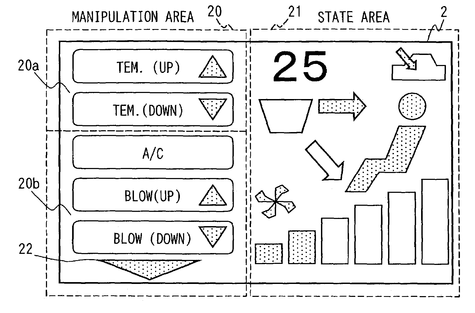
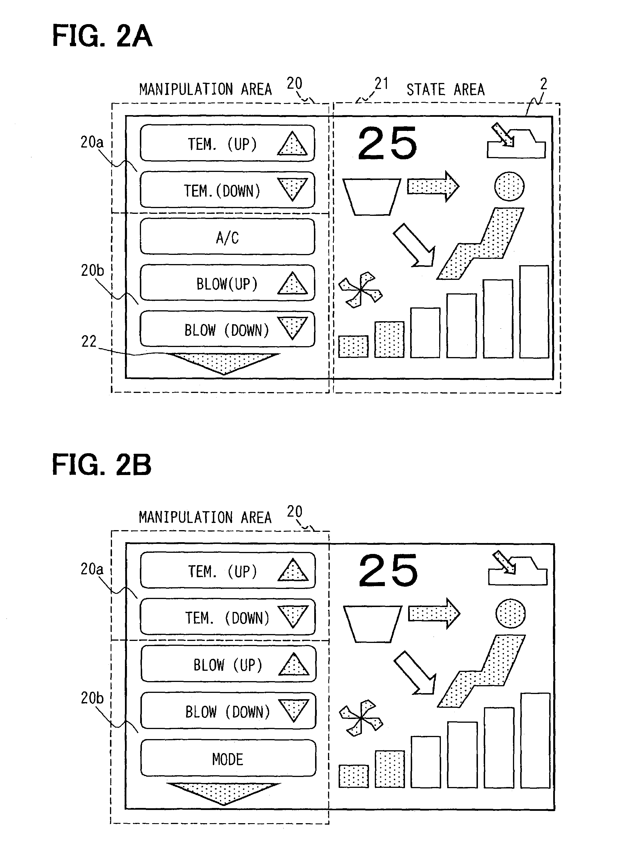
[0008]To achieve the above object, an in-vehicle-device control system is provided with the following. A display is disposed for displaying a plurality of manipulation items. Here, the display includes a variable area and a constant area. A first part of the manipulation items are displayed in the variable area. A second part of the manipulation items are displayed in the constant area. A selecting area is disposed for the user to select a necessary manipulation item from the manipulation items displayed on the display. An in-vehicle device is controlled to operate correspondingly to the necessary manipulation item selected by the user. Furthermore the first part of the manipulation items in the variable area are altered based on use condition for the first part of the manipulation items. This structure enables a necessary manipulation item to be properly displayed, so that the user can easily and quickly search for the necessary manipulation item.

Problems solved by technology

It is therefore difficult for the user to quickly select a necessary item, which results in involving a useless manipulation period up to completing to operate a necessary in-vehicle device.

Method used


Image

  • In-vehicle-device control system varying manipulation item display
  • In-vehicle-device control system varying manipulation item display
  • In-vehicle-device control system varying manipulation item display

Examples


first embodiment

[0018](First Embodiment)

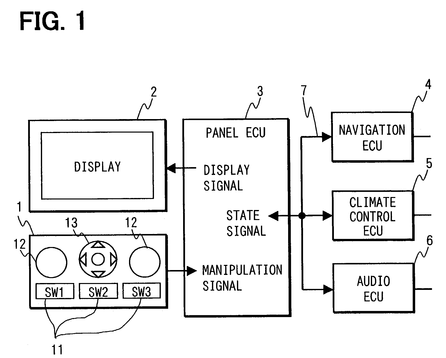
[0019]An in-vehicle-device control system as an embodiment of the present invention will be explained. As shown in FIG. 1, the in-vehicle-device control system includes a panel ECU 3, a manipulation panel 1, and a display 2. The panel ECU 3 is communicated with the manipulation panel 1 and the display 2. The panel ECU 3 is also communicated with other ECUs 4, 5, 6 controlling other in-vehicle devices via a multiplex signal line 7.

[0020]The manipulation panel 1 includes a set of function keys 11, a dial 12, and a directional switch 13. The set of the function keys 11 are formed of push switches SW1, SW2, SW3 that are used for calling manipulation menus of a navigation system, an air-conditioner, and an audio, respectively. When the push switch SW2 is manipulated, a manipulation menu of the air-conditioner is shown in the display 2.

[0021]The dial 12 is used for manipulating adjustment of sound volume in the audio or modification of scale of a road map in the na...

second embodiment

[0038](Second Embodiment)

[0039]In a second embodiment, the manipulation items in the variable area 20b are altered based on at least one of use conditions including a day of the week, a season, a time zone of the day, an interior and exterior temperature, and a user state, while they are altered based on the frequency of user's selection in the first embodiment. Referring to FIG. 4, processing for altering displayed manipulation items in the variable area 20b based on the use condition will be explained.

[0040]Manipulating an air-conditioner is explained as an instance below. In a rainy season, windows of the interior of a vehicle are often fogged up. A user is apt to select a manipulation item for switching to a mode of introducing an exterior air regarding interior / exterior air switching or a manipulation item for switching to “DEF(defog).” Namely, a season affects selection of the manipulation item.

[0041]When a user smokes a cigarette during a commuting time zone, the user is apt ...

third embodiment

[0050](Third Embodiment)

[0051]In a third embodiment, the manipulation items are enabled to be altered only under predetermined condition. Namely, if the manipulation item to be displayed is altered according to every change in the selection frequency, it is sometimes less comfortable for the user to select the manipulation item. Consequently, a predetermined condition for altering the manipulation item is set so as to prevent rapid altering of the manipulation item. The user is thereby prevented from being confused at searching for the necessary manipulation item. This processing will be explained below referring to FIG. 5.

[0052]At Step 30 in FIG. 5, whether re-altering condition for altering order of the manipulation items is met is determined. The re-altering condition is related to period or frequency, e.g., whether an elapsed period from the preceding altering of the manipulation items exceeds a predetermined elapsed period, or whether difference in number of times of selection ...


PUM


Abstract

A manipulation display area and an operation state display area are disposed in a display. The manipulation display area is divided into a constant area and a variable area. The constant area includes manipulation items to be most frequently selected by a user, while the variable area includes manipulation items to be altered according to use condition. Thereby the user can easily reach a necessary manipulation item among a lot of the manipulation items.

Description

CROSS REFERENCE TO RELATED APPLICATIONS[0001]This application is based on and incorporates herein by reference Japanese Patent Application No. 2002-141061 filed on May 16, 2002.FIELD OF THE INVENTION[0002]The present invention relates to an in-vehicle-device control system where a user searches a manipulation display for a necessary manipulation item among a plurality of manipulation items.BACKGROUND OF THE INVENTION[0003]In an instrument panel in a vehicle, there are a manipulation area, formed of a plurality of switches for manipulating in-vehicle devices, and a displaying area, for displaying operating states of the in-vehicle devices. Recently, appearance of an intelligent transport system (ITS) represented by a navigation system and an adaptive cruise control system (ACC) exhibits increasing of the number of the in-vehicle devices and enhancing performance of the in-vehicle devices. The switches for manipulating the in-vehicle devices thereby have a tendency to increase. Theref...

Claims


Application Information

Patent Timeline
IPC IPC(8): B60Q1/00B60R16/02B60K37/06G05B15/02G05B23/02
CPCG05B15/02
Inventor ITO, YUJIKOSHOBU, NOBUAKIKAWAI, TAKAYOSHIKAMIYA, AKIRA
Owner DENSO CORP
Learn More