
Fused electrical disconnect device

a technology of fused electrical disconnect and fused device, which is applied in the direction of fuse disposition/arrangement, emergency protective device, electrical apparatus, etc., can solve the problems of switching the type of overload protection device used, and it is not possible to install circuit breakers in the original setup of the power distribution system

Inactive Publication Date: 2006-02-14
CANADIAN SHUNT IND
View PDF35 Cites 36 Cited by
  • Summary
  • Abstract
  • Description
  • Claims
  • Application Information

AI Technical Summary

Benefits of technology

[0034]The present invention provides advantages in that the connection interface of the fused electrical disconnect device includes plug-in type connectors similar to those commonly used in circuit breakers. The plug-in type connectors allow the fused electrical disconnect device to be front mounted in a power distribution panel adapted to accommodate plug-in type connectors quickly and easily. This of course avoids having to wire the fused electrical disconnect device between the load device and the power source supply buss.
[0035]The present invention also provides advantages in that the fused electrical disconnect device generates an alarm signal whenever power to the load device is interrupted. Power interruption can be a result of a blown fuse within the fused electrical disconnect device or a removal of the fuse holding cartridge from the housing. Since the fused electrical disconnect provides an alarm signal when the fuse holding cartridge is removed from the device housing, situations where the fuse holding cartridge has been removed from the housing but not replaced can be detected.

Problems solved by technology

As a result, it has not been possible to install circuit breakers in power distribution systems originally set up for use with fused electrical disconnect devices.
Thus, switching the type of overload protection devices used in power distribution systems in the past has been costly and time consuming, making it impractical.

Method used


Image

  • Fused electrical disconnect device
  • Fused electrical disconnect device
  • Fused electrical disconnect device

Examples


Embodiment Construction

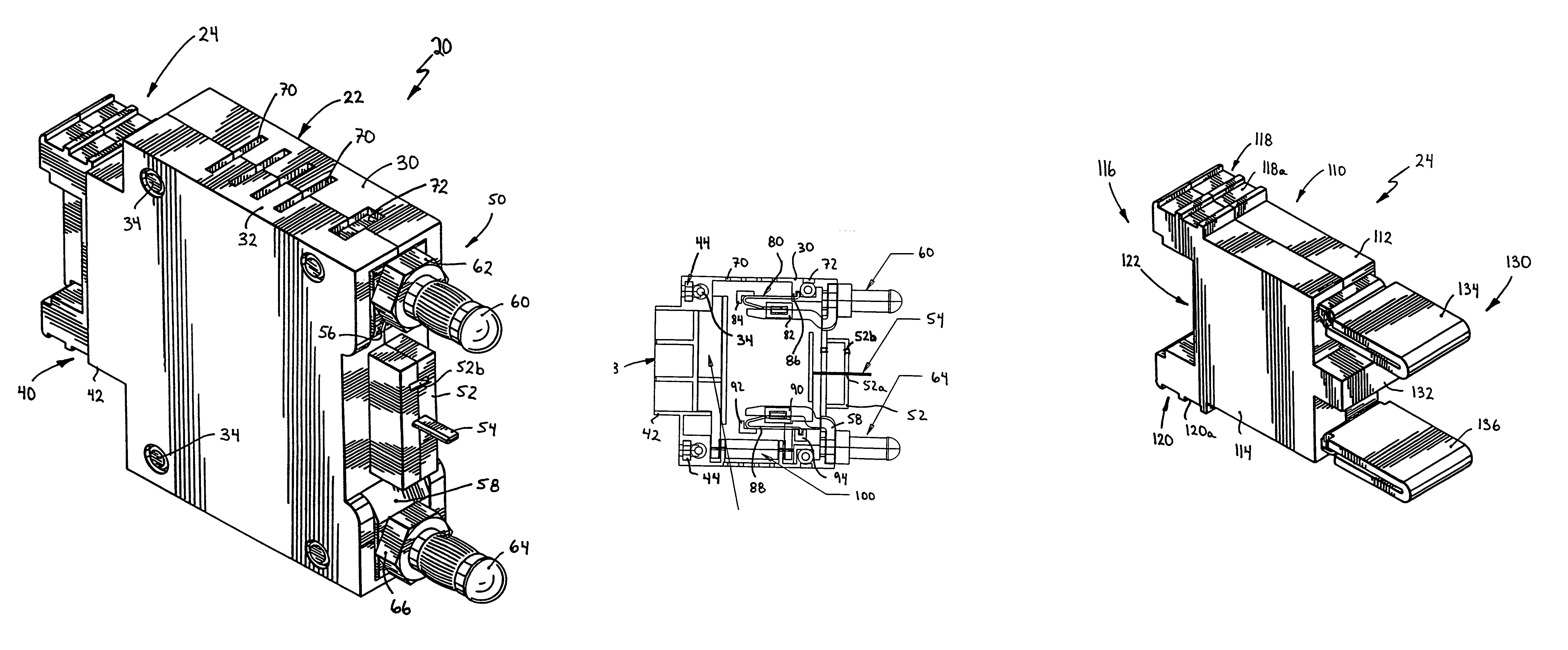
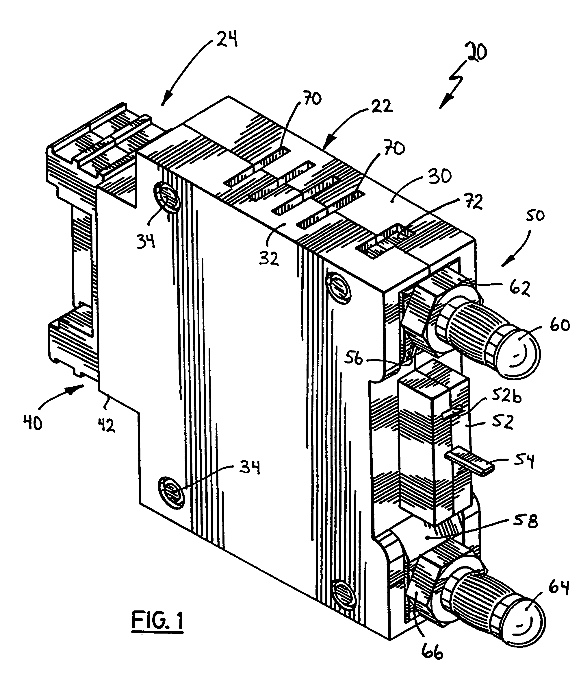
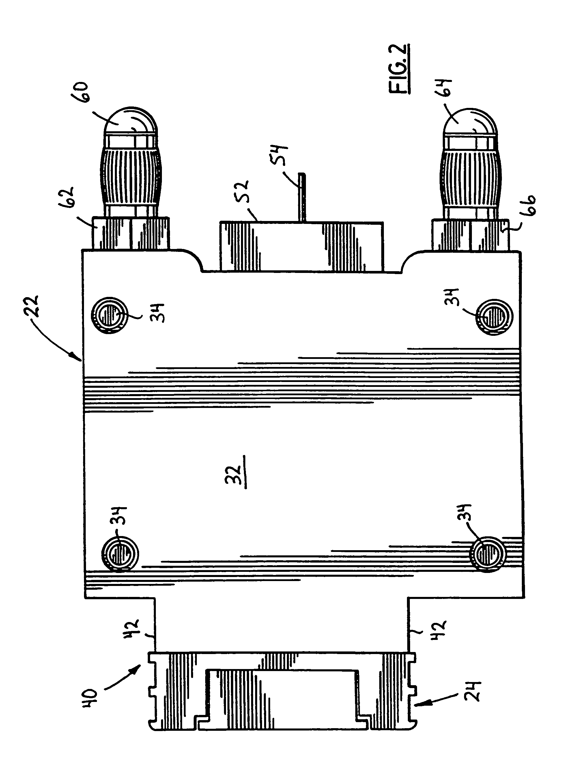
[0048]Turning now to FIGS. 1 and 2, a fused electrical disconnect device in accordance with the present invention is shown and is generally indicated to by reference numeral 20. Fused electrical disconnect device 20 is designed to be plugged into a power distribution panel interconnecting a power source supply buss and a load device. The fused electrical interconnect device provides a fused conductive path for current flowing between the power source supply buss and the load device. If an overload or fault condition occurs and the current flowing through the fused electrical interconnect device exceeds its rating, current flow to the load device is interrupted and an alarm signal, signifying the overload or fault condition is generated. Specifics of the fused electrical disconnect device 20 will now be described.

[0049]As can be seen, in this embodiment fused electrical disconnect device 20 is compact and generally resembles a conventional circuit breaker. The fused electrical discon...


PUM


Abstract

A fused electrical disconnect device comprises a housing and line and load connectors extending from one side of the housing. A line buss is disposed within the housing and is electrically connected to the line connector. A load buss is also disposed within the housing and is electrically connected to the load connector. A fuse holding cartridge is removably insertable into the housing. The fuse holding cartridge includes a body and line and load terminal blades extending from one side of the body. The line terminal blade contacts the line buss and the load terminal blade contacts the load buss when the fuse holding cartridge is inserted into the housing. A load protection fuse is removably insertable between the line and load terminal blades to establish an electrical current path between the line and load terminal blades.

Description

[0001]This application claims priority to Ser. No. 09 / 725,335, filed Nov. 29, 2000, now U.S. Pat. No. 6,771,477, entitled “Fused Electrical Disconnect Device”, which is specifically incorporated by reference herein.FIELD OF THE INVENTION[0002]The present invention relates generally to low voltage, high current electrical power distribution systems, and more particularly to a fused electrical disconnect device for use in an electrical power distribution system.BACKGROUND OF THE INVENTION[0003]Power distribution systems, such as telephone switching offices in telecommunications systems are often constructed on a large scale to serve many customers. Since telephone communications are essential for most businesses, it is necessary to ensure that telecommunications systems of this nature are highly reliable. To keep telecommunications systems operational in the event of power interruptions, most telecommunications systems typically include a plurality of high-capacity storage batteries t...

Claims


Application Information

Patent Timeline
IPC IPC(8): H01H85/50H01H85/48H01H85/20H01H85/045H01H85/147H01H85/30H01H85/54H01H85/56
CPCH01H85/547H01H85/306H01H85/56
Inventor MILANCZAK, EDWIN
Owner CANADIAN SHUNT IND
Learn More