
Packaging system for a component including a compressive and shock-absorbent packing insert

Inactive Publication Date: 2006-02-14
IBM CORP
View PDF11 Cites 45 Cited by
  • Summary
  • Abstract
  • Description
  • Claims
  • Application Information

AI Technical Summary

Benefits of technology

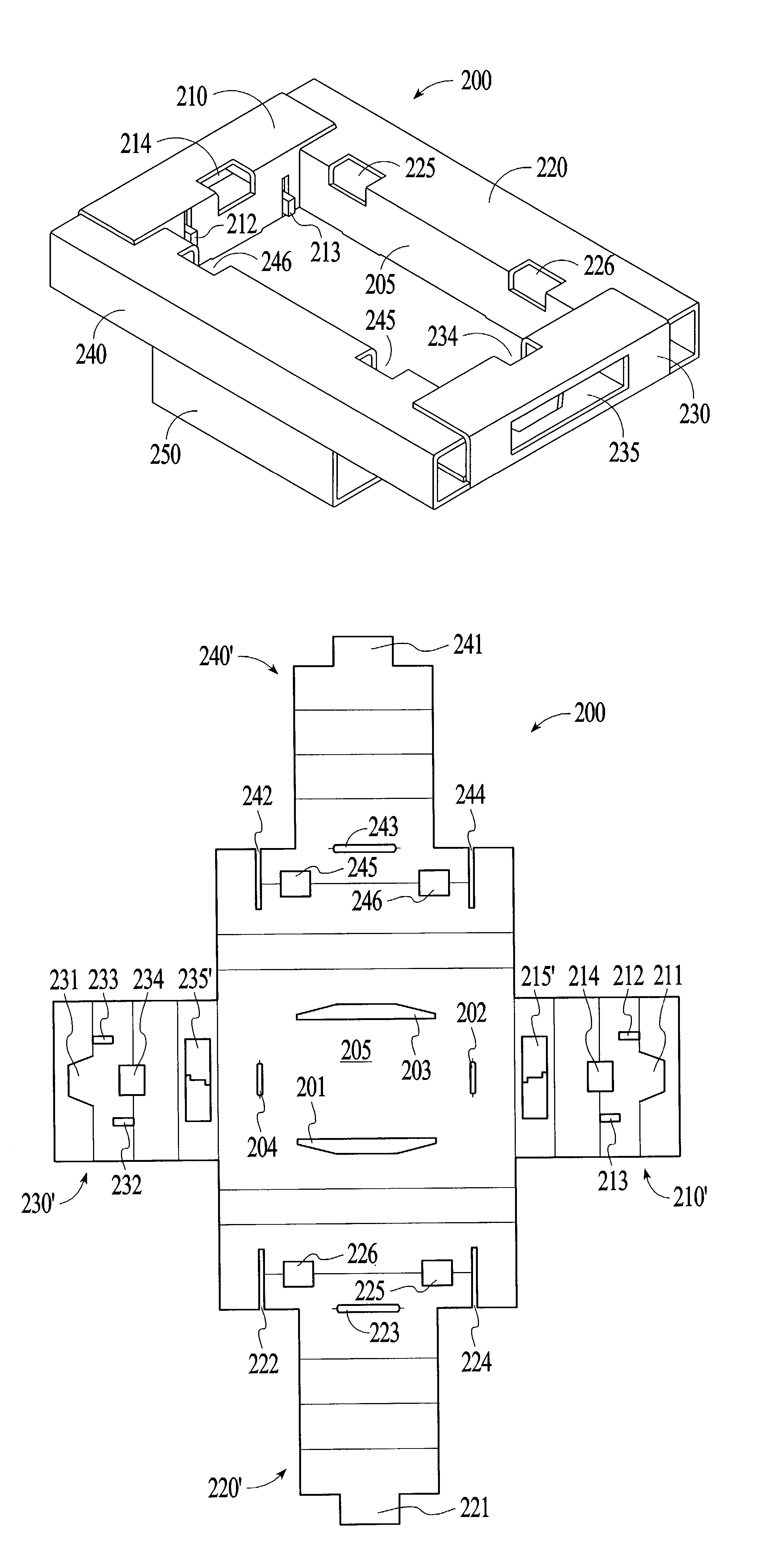
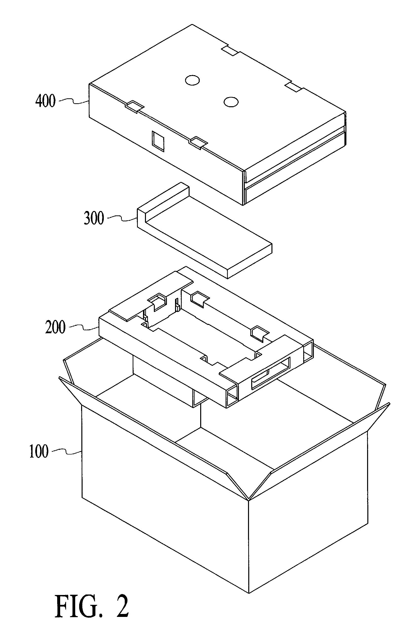
[0005]A packaging system for a component is disclosed. The packaging system comprises a box and a compressible and shock-absorbent packing insert. The packing insert is placed in the box after nesting a component within the insert. The insert comprises a main panel, a first end tube hingedly coupled to the main panel, a second end tube hingedly coupled to the main panel opposite the first end tube, a first side tube hingedly coupled to the main panel, the first side tube being adjacent to the first end tube and a second side tube hingedly coupled to the main panel, the second side tube being adjacent to the second end tube and opposite the first side tube wherein the first and second side tube panels and the first and second side tube panels include at least one cutout to enhance the flexing capability of the packing insert.
[0006]Accordingly, the packing insert in accordance with the present invention employs low cost, environment friendly material to protect fragile components from any potential damage that can be caused during the shipping process.

Problems solved by technology

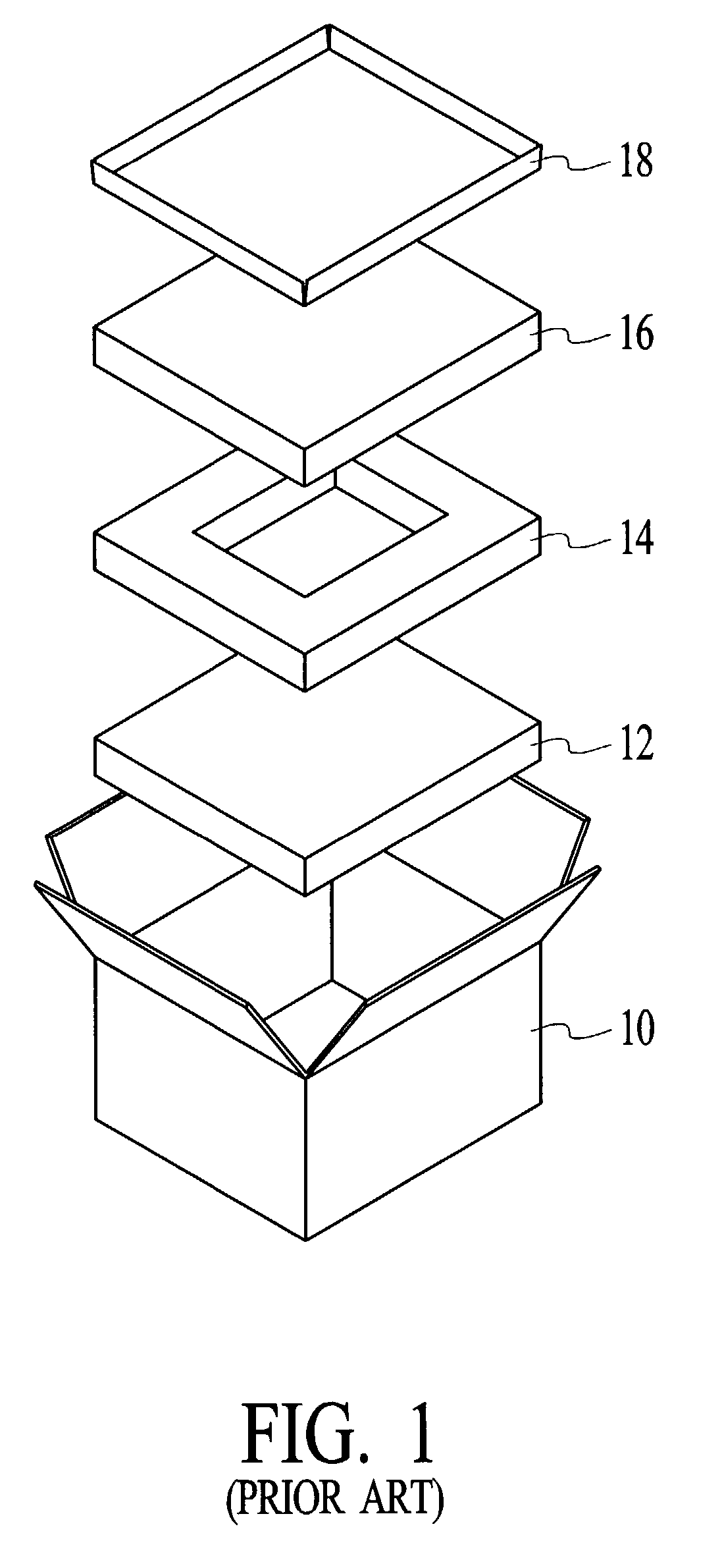
However, as previously mentioned, a drawback to this approach is the high cost of the polyurethane material, as well as the fact that polyurethane is not biodegradable and thus not environment friendly.

Method used


Image

  • Packaging system for a component including a compressive and shock-absorbent packing insert
  • Packaging system for a component including a compressive and shock-absorbent packing insert
  • Packaging system for a component including a compressive and shock-absorbent packing insert

Examples


Embodiment Construction

[0018]The present invention relates to a packing insert for protecting an article. The following description is presented to enable one of ordinary skill in the art to make and use the invention and is provided in the context of a patent application and its requirements. Various modifications to the preferred embodiment and the generic principles and features described herein will be readily apparent to those skilled in the art. Thus, the present invention is not intended to be limited to the embodiment shown but is to be accorded the widest scope consistent with the principles and features described herein.

[0019]The preferred embodiment of the present invention is a corrugated packing insert for protecting a highly fragile component (i.e., hard disk drive) during shipment. Accordingly, the packing insert in accordance with the present invention employs a low cost, environment friendly material (i.e. corrugated material) to protect fragile components from any potential damage that c...


PUM

PropertyMeasurementUnit
Biodegradabilityaaaaaaaaaa
Compressibilityaaaaaaaaaa

Abstract

A packaging system for a component is disclosed. The packaging system comprises a box and a compressible and shock-absorbent packing insert. The packing insert is placed in the box after nesting a component within the insert. The insert comprises a main panel, a first end tube hingedly coupled to the main panel, a second end tube hingedly coupled to the main panel opposite the first end tube, a first side tube hingedly coupled to the main panel, the first side tube being adjacent to the first end tube and a second side tube hingedly coupled to the main panel, the second side tube being adjacent to the second end tube and opposite the first side tube wherein the first and second side tube panels and the first and second side tube panels may include at one or more cutouts to enhance the flexing capability of the packing insert. Accordingly, the packing insert in accordance with the present invention employs low cost, environment friendly material to protect fragile components from any potential damage that can be caused during the shipping process.

Description

FIELD OF THE INVENTION[0001]The present invention relates to tube / box inserts and more specifically to a packing insert to be used with shock-sensitive hard disk drives or similar components of varying sizes.BACKGROUND OF THE INVENTION[0002]Previous approaches to shipping fragile components (i.e., hard drives) have typically utilized substances such as resilient foam, as well as adhesives and other non-recyclable materials when packaging such components.[0003]For an example of a typical packaging system, please refer now to FIG. 1. FIG. 1 is an exploded view of a typical packaging system for fragile components such as a hard drive. This approach utilizes a polyurethane bottom cushion 12, a polyurethane middle cushion 14, a polyurethane top cushion 16 and a corrugated tray 18, all of which fit into a corrugated carton 10. Utilizing this approach, the component to be shipped (not shown) is inserted between the polyurethane top cushion 16 and the polyurethane bottom cushion 12, through...

Claims


Application Information

Patent Timeline
IPC IPC(8): B65D81/02B65D5/50B65D85/68
CPCB65D5/5069B65D2585/6837
Inventor MARESH, MARK EDMUNDMILLER, JEFFREY JAYSTEGNER, ERIC ALLENSTEGNER, ROBERT W.TURNER, CHRISTOPHER MICHAEL
Owner IBM CORP
Learn More