
Cool air inhaler

a technology of inhaler and cool air, which is applied in the direction of heating types, combustion types, domestic cooling devices, etc., can solve the problems of difficulty breathing, inability to concentrate on tasks, and severe sleep loss or res

Inactive Publication Date: 2006-02-14
ATLANTIC RES GROUP
View PDF13 Cites 16 Cited by
  • Summary
  • Abstract
  • Description
  • Claims
  • Application Information

AI Technical Summary

Benefits of technology

"The present invention is a cool air inhaler designed to treat croup. It includes a body with an enclosed space that conforms to the patient's face. The inhaler has an air chamber with an exhaust vent and an ice reservoir to cool and moisturize the air. The intake air is cooled and moistened as the patient breathes in, and the exhaust air is vented out. The air passage has a one-way intake valve and a one-way exhaust valve. The inhaler also has an air intake tube with an intake opening in the bottom of the body and an output above the ice reservoir. The technical effect of this invention is to provide a cool, moisturized air inhalant for patients with croup that can help alleviate symptoms."

Problems solved by technology

There are a number of diseases and conditions that may cause upper respiratory tract symptoms that, while they may not rise to a ciritical condition, may result in notable discomfort, such as severe coughing, that can result, for example, in exhaustion, severe loss of sleep or rest, inability to concentrate on tasks, and so on.
One of the most common of such diseases is “croup”, which is a viral infection of the upper and lower airways that can be caused by a range of viruses and that causes difficulty in breathing, especially when inhaling.
The symptoms of croup may initially be similar to those of the common cold, but croup will cause swelling of the lining of the airway, causing the airway to narrow and making breathing difficult, resulting in, for example, a barking cough and hoarseness.
All of these methods, however, suffer from the same disadvantage of being cumbersome and inconvenient to use.
For example, humidifiers, cool mist vaporizers or ultrasonic nebulizers require confining the patient to a relatively small area, as does the use of a hot shower, which confines the patient to a space that is relatively smaller and that can be very uncomfortable.
In a like manner, going outdoors into cooler and perhaps moister air is useful only if the air outside is in fact cooler and moister; this method may not be practical in, for example, Arizona in the summer.

Method used


Image

  • Cool air inhaler
  • Cool air inhaler

Examples


Embodiment Construction

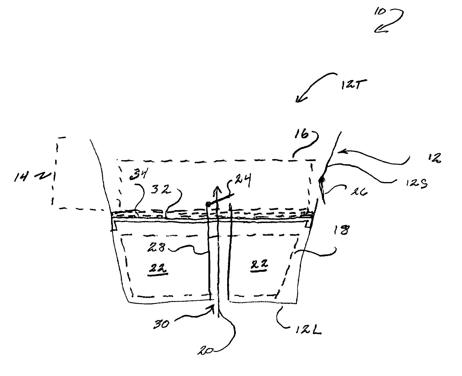
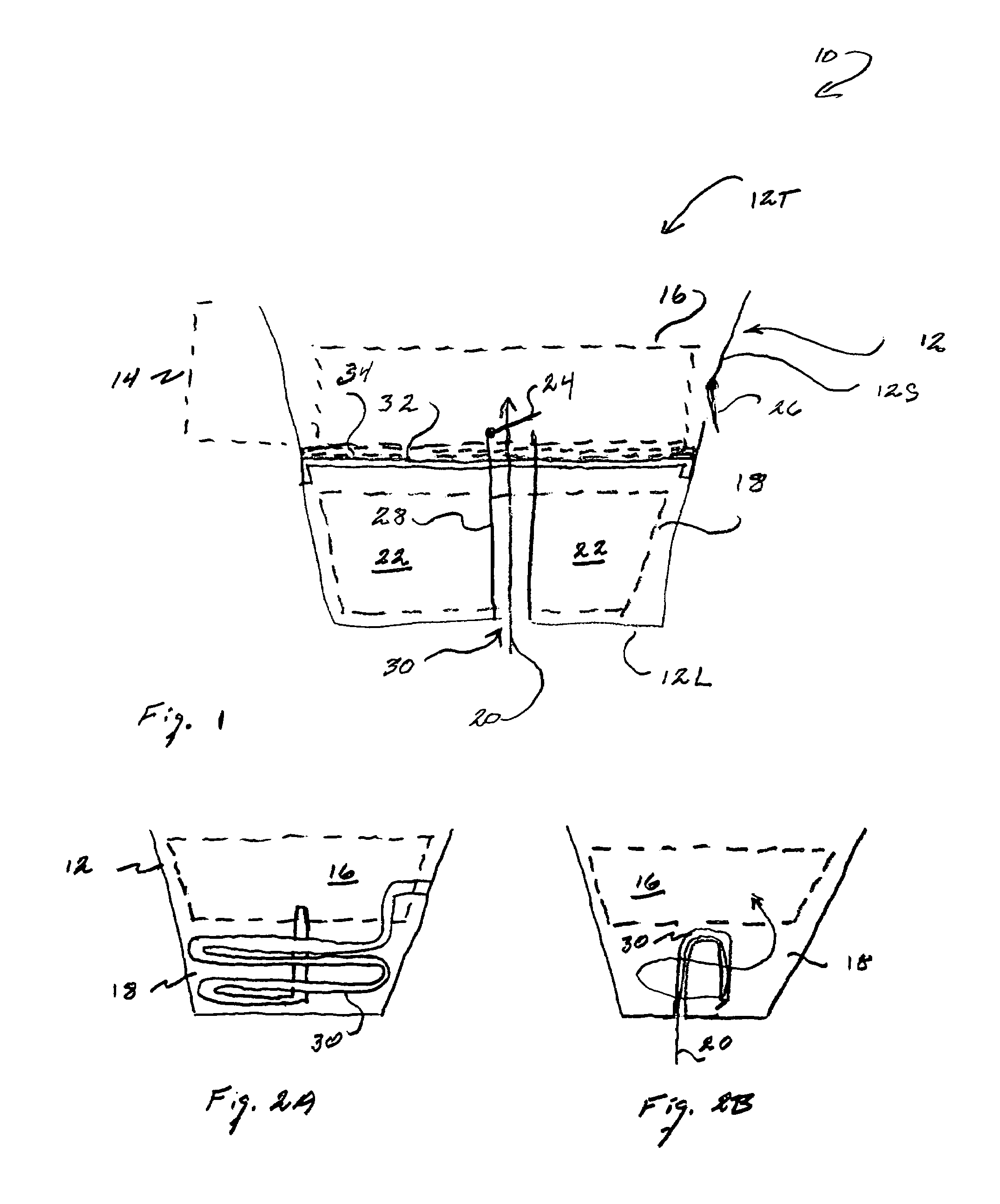
[0015]Referring to FIG. 1, therein is shown a diagrammatic cross section view of a Cool Air Inhaler (Inhaler) 10 of the present invention. As illustrated therein, a Inhaler 10 includes a generally cup-shaped Body 12 having a generally cylinderical Side Wall 12S, a Lower Wall 12L closing off the bottom of Side Wall 12S, and an open Top 12T, thereby forming an enclosed space having an open top. As indicated, the upper portion of Body 12 forms having a Mask 14 portion wherein open Top 12T generally fits over a patient's mouth and nose. For this purpose, the upper portion of Body 12 is either shaped to the average general lower face contours of a patient or is sufficiently resiliently deformable to generally conform to the lower face contours of a patient under relatively low force.

[0016]In this regard, it should be noted that the confomity of Mask 14 to a patient's lower facial contours need only be approximate as Inhaler 10 is not delivering valuable or rare gases or medicated gases t...


PUM


Abstract

A cool air inhaler for use in treating croup, having a body having at least one side wall and a bottom wall forming an enclosed space open at an upper portion of the body wherein the upper portion of the body is adapted to generally conform to contours of a lower part of a patient face. An air chamber is formed in an upper part of the body and has an exhaust vent for exhausting the patient's exhaled air to an exterior space while an ice reservoir is formed in a lower part of the body to contain ice and meltwater from the ice and an air passage is connected from the exterior space and passing through the ice reservoir to conduct air to the air chamber.

Description

FIELD OF THE INVENTION[0001]The present invention relates to a medical inhalation device for relief fro symptoms of respiratory illnesses and, in particular, to a cool air inhaler for treatment of croup by non-medical personnel, including a patient.BACKGROUND OF THE INVENTION[0002]There are a number of diseases and conditions that may cause upper respiratory tract symptoms that, while they may not rise to a ciritical condition, may result in notable discomfort, such as severe coughing, that can result, for example, in exhaustion, severe loss of sleep or rest, inability to concentrate on tasks, and so on.[0003]One of the most common of such diseases is “croup”, which is a viral infection of the upper and lower airways that can be caused by a range of viruses and that causes difficulty in breathing, especially when inhaling. The symptoms of croup may initially be similar to those of the common cold, but croup will cause swelling of the lining of the airway, causing the airway to narro...

Claims


Application Information

Patent Timeline
Patent Type & Authority Patents(United States)
IPC IPC(8): A61M16/00A61M15/08A62B7/00A62B9/02F24F5/00A61M16/10
CPCA61M16/1075A61M2205/366A61M2205/3606
Inventor DONOHUE, TIMOTHY J.
Owner ATLANTIC RES GROUP
Learn More