
Ventilation interface for sleep apnea therapy

a technology for sleep apnea and ventilation interface, which is applied in the field of ventilation interface for sleep apnea therapy, can solve the problems of affecting the patient's breathing, affecting the patient's physical and mental health, and affecting the patient's sleep apnea, so as to avoid drying and burning of the patient's nasal airways, and increase the internal diameter

Inactive Publication Date: 2006-02-14
SALTER LABS LLC
View PDF84 Cites 272 Cited by
  • Summary
  • Abstract
  • Description
  • Claims
  • Application Information

AI Technical Summary

Benefits of technology

"The invention is a ventilation interface for sleep apnea therapy that uses nasal inserts to deliver positive airway pressure. The nasal inserts are thin-walled and flexible, with a unique design that allows them to seal against the nares without needing a harness or head strap. The interface includes a bleed port to prevent whistling noises and a valve to control the flow of air. The nasal inserts can also be used without a mechanical ventilation supply or positive airway pressure. The invention provides a more comfortable and effective treatment for sleep apnea."

Problems solved by technology

Sleep apnea is a potentially lethal affliction in which breathing stops recurrently during sleep.
Sleep apnea frequently results in fitful periods of both day and night sleeping with drowsiness and exhaustion, leaving the patient physically and mentally debilitated.
However, there are problems with both of these interfaces.
The face mask requires a harness, headband, or other headgear to keep the mask in position, which many patient's find uncomfortable, particularly when sleeping.
The face mask must seal the mask against the patient's face, and may cause irritation and facial sores, particularly if the patient moves his head while sleeping, causing the mask to rub against the skin.
Face masks are also position dependent, and may leak if the mask changes position with movement of the patient's head.
This strips moisture from the mucosal wall during inspiration, thereby causing drying and a burning sensation.
These factors will often result in the patient's removal of the mask and discontinuance of positive airway pressure therapy.
Nasal pillows require a headband or harness to maintain the pressure, resulting in the same patient discomfort noted with face masks.
Therefore, pressurized air must pass through a constricted port, increasing the velocity of airflow, with resultant drying and burning of the nasal airways.
An increase in driving pressure does not fully compensate for the loss in the number of air molecules available.
A further problem with existing ventilation devices is that the carbon dioxide bleed ports for venting exhaled gases are noisy on both nasal face masks and nasal pillows.
The whistling noise that occurs while utilizing such devices can prove quite annoying to the patient, awakening the patient and causing the patient to discontinue use of the ventilation device.

Method used


Image

  • Ventilation interface for sleep apnea therapy
  • Ventilation interface for sleep apnea therapy
  • Ventilation interface for sleep apnea therapy

Examples


Embodiment Construction

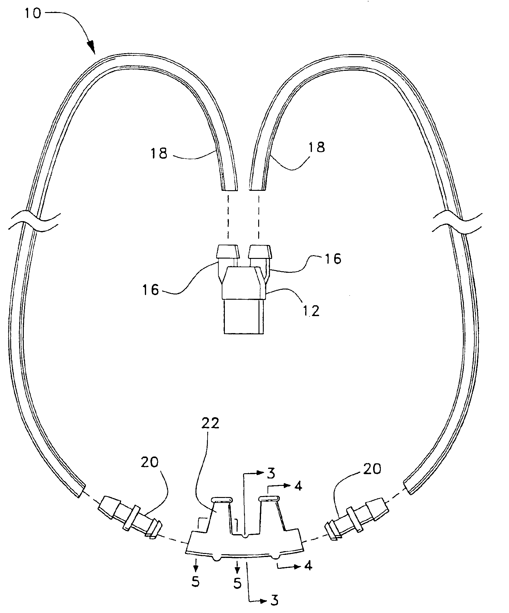
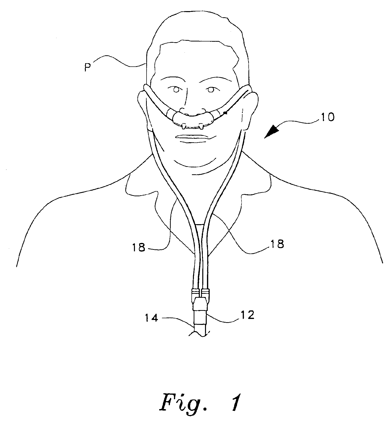
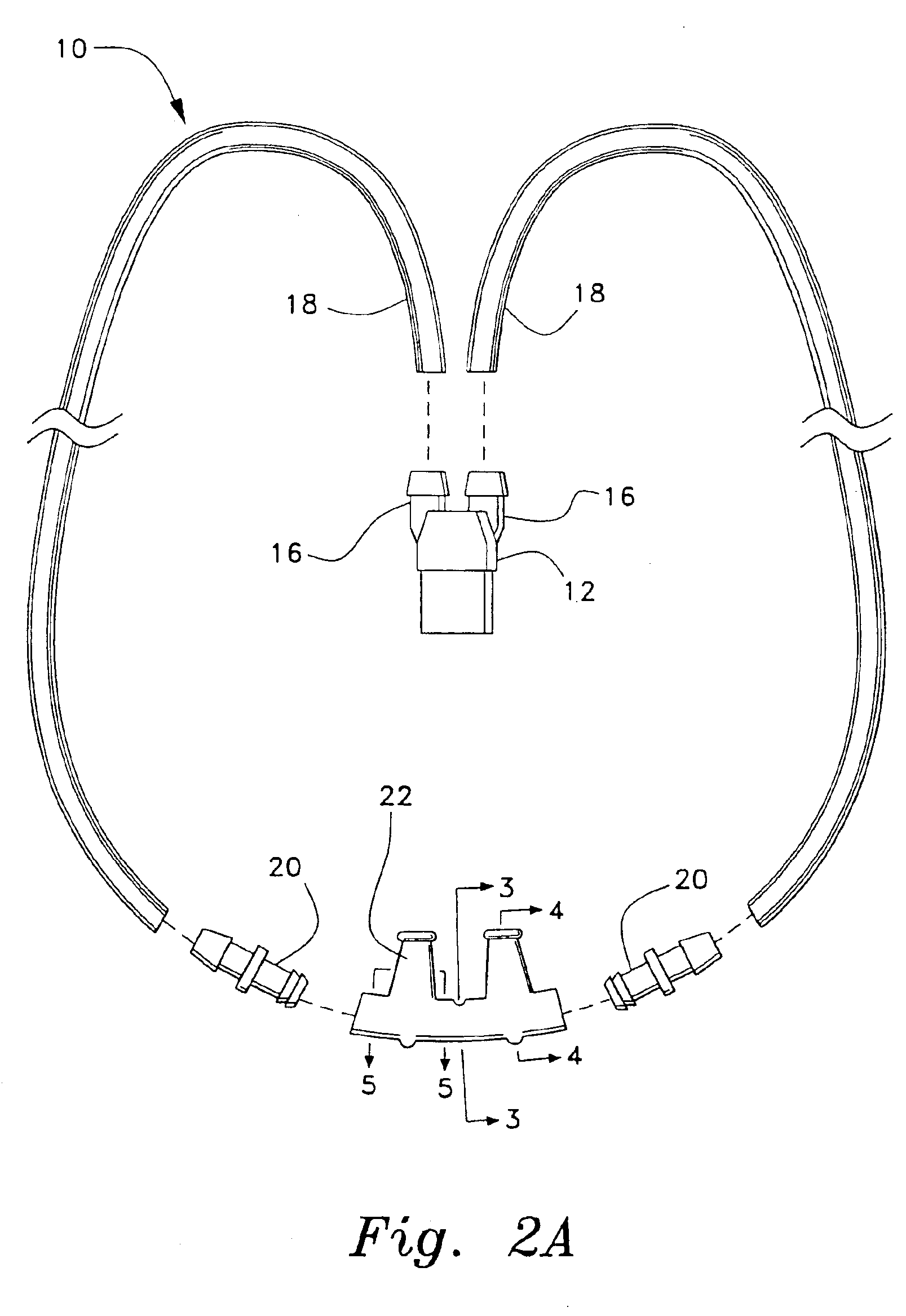
[0043]The present invention is a ventilation interface for sleep apnea therapy, designated generally as 10 in the drawings. The ventilation interface 10 provides an interface for connecting a ventilation device which provides positive airway pressure (either continuous, bilevel, or intermittent) with the patient's airways. As shown in FIGS. 1 and 2A, the ventilation interface 10 includes a conventional adapter or Y-connector 12 having a first end adapted to receive a supply hose 14 from a mechanical ventilator (not shown) and a second end having a pair of ports 16 with barbed connectors for attachment to two supply tubes 18. Supply tubes 18 may be, e.g., 0.3125″ ID (inside diameter) flexchem tubing, made of polyvinyl chloride or other conventional gas supply tubing. For sleep apnea therapy, the mechanical ventilator will usually supply room air at a pressure of between five and fifteen centimeters of water. The room air may be supplemented with oxygen if desired by splicing an oxyge...


PUM


Abstract

The ventilation interface for sleep apnea therapy interfaces a ventilation device to the patient's airways. The ventilation interface includes a pair of nasal inserts made from flexible, resilient silicone which are oval shaped in cross-section and slightly tapered from a base proximal the ventilation supply to the distal tip end. A bead flange is disposed about the exterior of each insert at the distal end of the insert. In one embodiment, a valve is disposed between the nasal inserts and a source of positive airway pressure, the valve having a rim with a one-way diaphragm pivotally attached to the valve body with an inflatable bladder depending from the rim which seals against an exit port during inspiration and deflates to uncover the exit port on expiration. Another embodiment has nasal inserts without positive airway pressure but with a removable filter in the inserts for filtering inspired air.

Description

CROSS REFERENCE TO RELATED APPLICATIONS[0001]This is a continuation of application 10 / 096,795 filed Mar. 14, 2002 which is now U.S. Pat. No. 6,776,162 which is a continuation-in-part of my prior application Ser. No. 10 / 044,925, filed Jan. 15, 2002 now U.S. Pat. No. 6,595,215 which is a continuation-in-part of my prior application Ser. No. 09 / 524,371 now U.S. Pat. No. 6,478,026 filed Mar. 13, 2000 which claims priority under 35 U.S.C. §119 to provisional application Ser. No. 60 / 124,323 filed on Mar. 13, 1999 and for each of which priority is claimed under 35 U.S.C. §120 and the entire contents of each are hereby incorporated by reference. Additionally this application claims priority under 35 U.S.C. §120 to co-pending applications Ser. No. 10 / 364,388 filed Feb. 12, 2003 and for which the entire contents are hereby incorporated by reference.BACKGROUND OF THE INVENTION[0002]1. Field of the Invention[0003]The present invention relates to ventilation devices, and particularly to a ventil...

Claims


Application Information

Patent Timeline
Patent Type & Authority Patents(United States)
IPC IPC(8): A61M15/00A61M16/06A61M16/10
CPCA61M16/0666A61M16/208A61M16/1045A61M2205/42A61M16/0816A61M16/1055A61M16/0616A61M16/0833A61M16/107
Inventor WOOD, THOMAS J.
Owner SALTER LABS LLC
Learn More