
System, method, and computer program product for optimization of a scene graph

Inactive Publication Date: 2006-02-07
ACTIVISION PUBLISHING
View PDF3 Cites 90 Cited by
  • Summary
  • Abstract
  • Description
  • Claims
  • Application Information

AI Technical Summary

Benefits of technology

[0012]The method of the invention includes the steps of receiving an input scene graph, creating the optimization process, applying the optimization process to the input scene graph, and post-optimization processing. The optimization process can be performed for any of a number of purposes, such as the enhancement of scene graph traversal time, the enhancement of drawing time, the reduction of memory usage, improved efficiency of data manipulation, and the targeting of a specific rendering platform.

Problems solved by technology

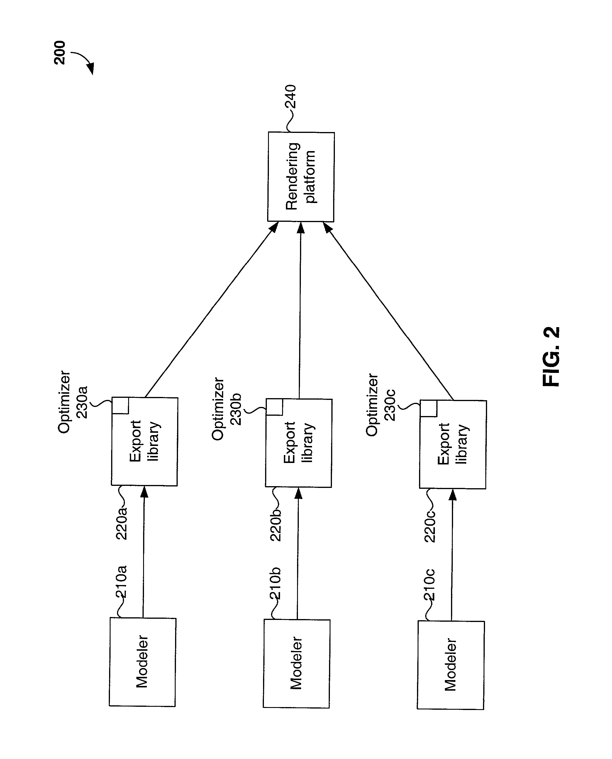
The arrangement of FIG. 2 is inherently redundant and inefficient.
The code representing software embodiments of the export libraries and optimizers is therefore repetitive.

Method used


Image

  • System, method, and computer program product for optimization of a scene graph
  • System, method, and computer program product for optimization of a scene graph
  • System, method, and computer program product for optimization of a scene graph

Examples


Embodiment Construction

[0028]A preferred embodiment of the present invention is now described with reference to the figures, where like reference numbers indicate identical or functionally similar elements. Also in the figures, the left-most digit of each reference number corresponds to the figure in which the reference number is first used. While specific configurations and arrangements are discussed, it should be understood that this is done for illustrative purposes only. A person skilled in the relevant art will recognize that other configurations and arrangements can be used without departing from the spirit and scope of the invention. It will be apparent to a person skilled in the relevant art that this invention can also be employed in a variety of other devices and applications.

Table of Contents

[0029]I. Overview[0030]II. System[0031]III. Process[0032]IV. Atomic Optimizations

[0033]A. Collapse Geometry

[0034]B. Collapse Hierarchy

[0035]C. Convert Image

[0036]D. Convert Transform

[0037]E. Create Bounding...


PUM


Abstract

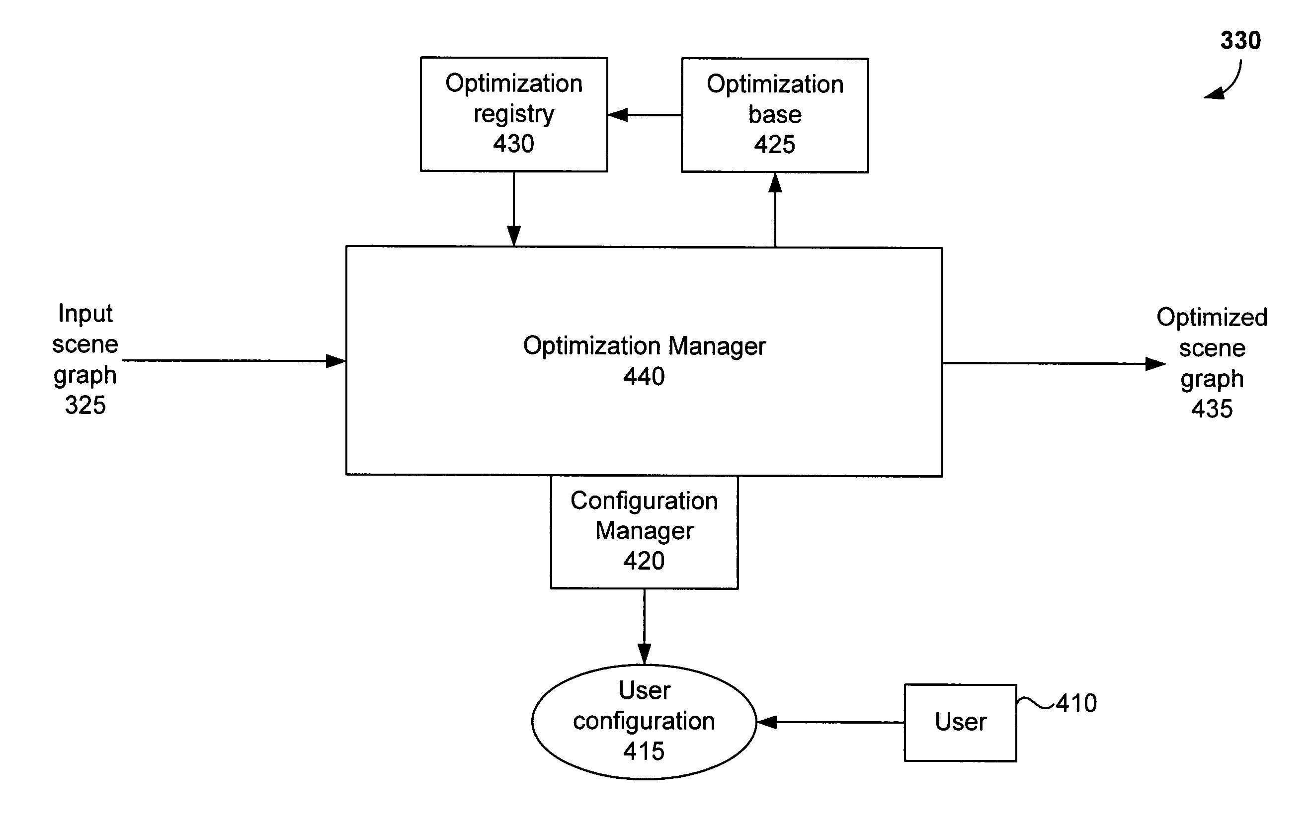
The invention described herein is a system, method, and computer program product for optimization of a scene graph. The system includes an optimization base that contains a set of specific atomic optimizations. The system also includes an optimization registry that lists each atomic optimization, parameters associated with each optimization, and priority information relating to the necessary order in which optimizations must be performed. The system also includes an optimization manager which creates, configures, and applies an optimization process to an input scene graph. The system further includes an optimization configuration module for accepting user input to the optimization process. The method includes the steps of receiving an input scene graph, creating the optimization process, applying the optimization process to the input scene graph, and post-optimization processing. The optimization process can be performed for any of a number of purposes, such as the enhancement of scene graph traversal time, the enhancement of drawing time, the reduction of memory usage, improved efficiency of data manipulation, and the targeting of a specific rendering platform.

Description

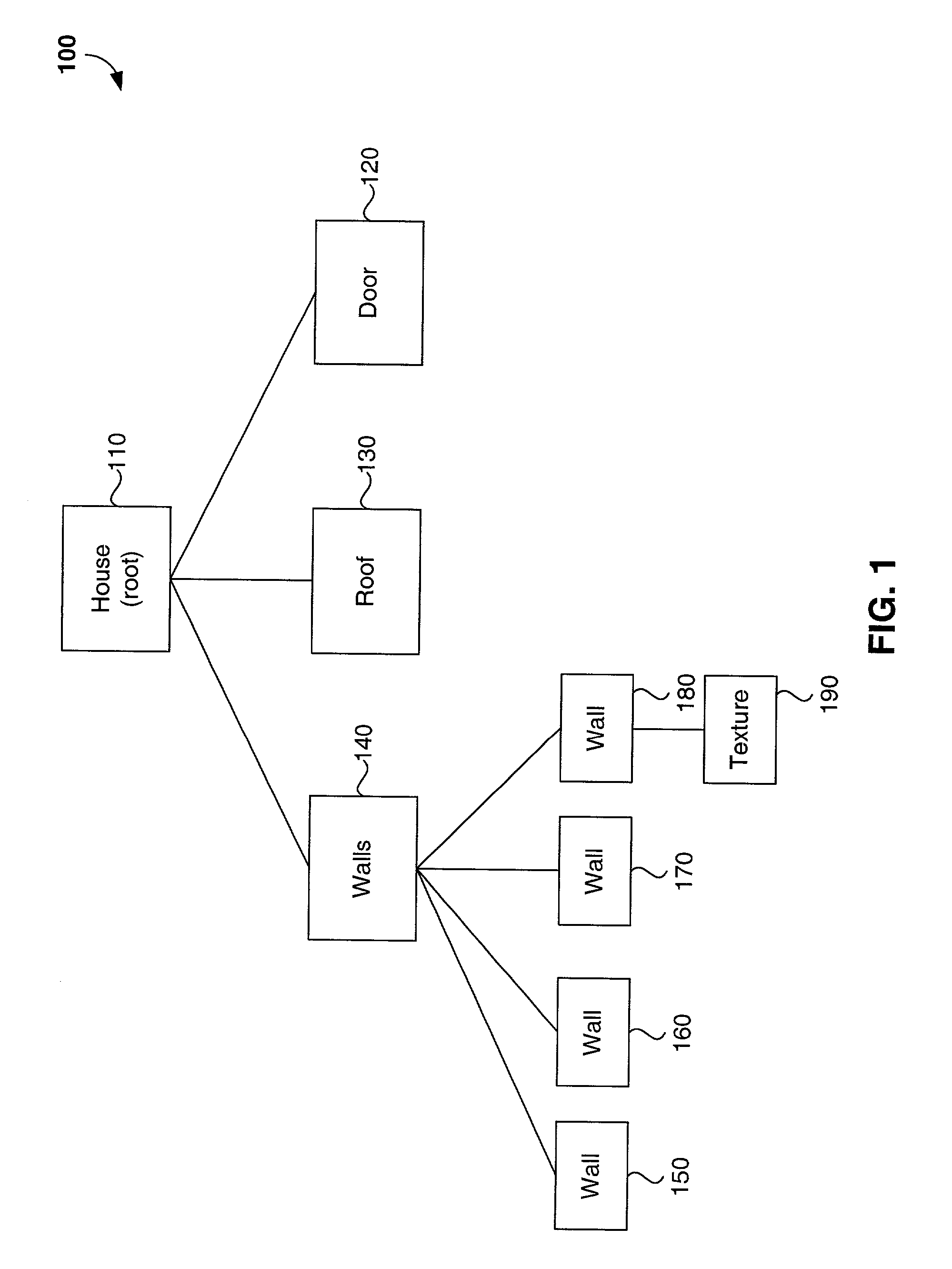
CROSS-REFERENCE TO RELATED APPLICATIONS[0001]Not applicable.STATEMENT REGARDING FEDERALLY-SPONSORED RESEARCH AND DEVELOPMENT[0002]Not applicable.REFERENCE TO MICROFICHE APPENDIX / COMPUTER PROGRAM LISTING APPENDIX[0003]Not applicable.BACKGROUND OF THE INVENTION[0004]1. Field of the Invention[0005]The invention described herein relates to computer graphics, and more particularly to data representation and rendering.[0006]2. Background Art[0007]In computer graphics, a scene can be modeled in a variety of ways. One way is through the use of a scene graph. The nodes of a scene graph represent features of the scene, such as physical objects and their attributes (e.g., colors and textures). The edges of a scene graph represent associations between the connected nodes. A node representing an object, for example, may be connected to a node representing a texture for that object. Scene graphs are often represented in object oriented languages such as C++. Scene graphs are well known in the com...

Claims


Application Information

Patent Timeline
IPC IPC(8): G06T17/00
CPCG06T17/005
Inventor BOUDIER, PIERRE S.
Owner ACTIVISION PUBLISHING
Learn More