
Pick-up and lay-down system and method

a pick-up and lay-down system and technology, applied in the direction of drilling rods, drilling casings, drilling pipes, etc., can solve the problems of poor heavy tubulars such as casings, and the inability to provide a suitable means for moving pipes, etc., to achieve the effect of improving the adaptability of prior art systems

Inactive Publication Date: 2006-02-07
FRANKS INT
View PDF5 Cites 35 Cited by
  • Summary
  • Abstract
  • Description
  • Claims
  • Application Information

AI Technical Summary

Benefits of technology

The present invention provides an apparatus and method for automatically lifting and lowering oilfield tubulars, especially large diameter tubulars, without damaging them during transportation. The invention addresses the problem of damage to sensitive areas of pipes, such as threads, caused by sharp lateral impacts and impacts to sensitive thread protecters during movement from the pipe rack to the rig floor. The invention is adaptable to different types of pipes and work environments, and can be used with various types of pipe handling systems. The invention provides a smooth and gradual transition for the pipe during transportation, reducing friction and impact damage.

Problems solved by technology

However, the prior art systems have problems relating to damage of the tubulars during this process.
Moreover, prior art systems are limited in their adaptability to the path of transportation typically to and from each particular rig floor, catwalk, and pipe rack arrangement.
However, the prior art does not provide a suitable means for moving pipes whereby they arrive at the rig floor virtually without experiencing sharp lateral impacts and / or friction damage to sensitive areas such as threads.
For instance, heavy tubulars such as casing, due to their very great weight and large diameter may be easily damaged by lateral impacts and / or even by impacts to thread protectors during movement from the pipe rack, to the cat walk, and then to the drill floor.
The transportation from a pipe rack to the rig floor often involves an irregular and difficult path for moving heavy items.

Method used


Image

  • Pick-up and lay-down system and method
  • Pick-up and lay-down system and method
  • Pick-up and lay-down system and method

Examples


Embodiment Construction

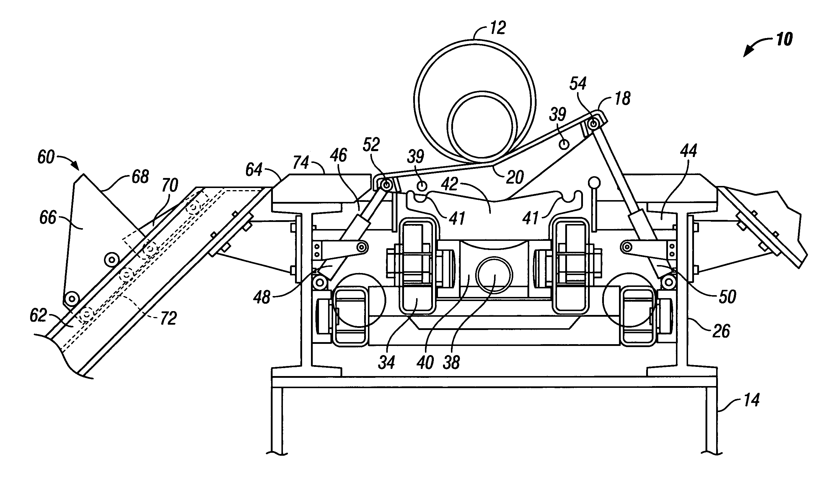
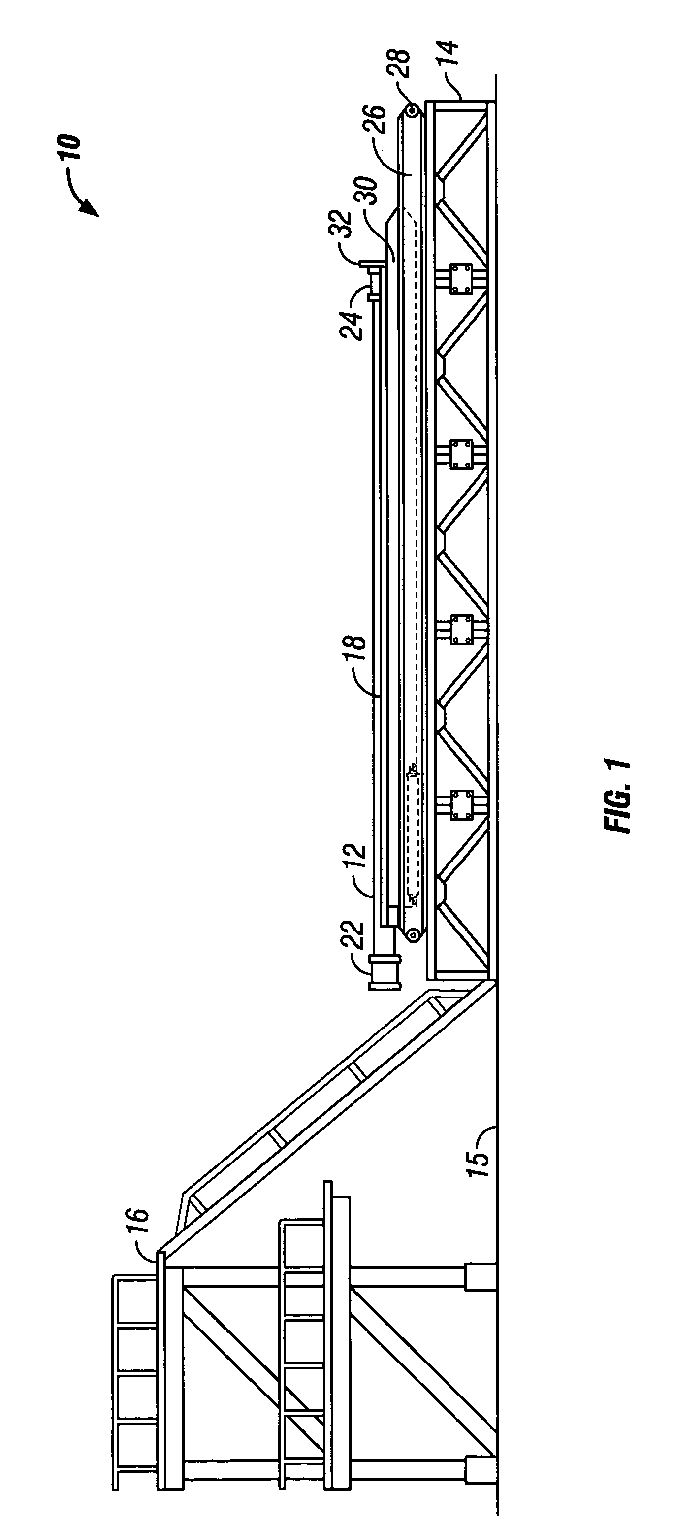
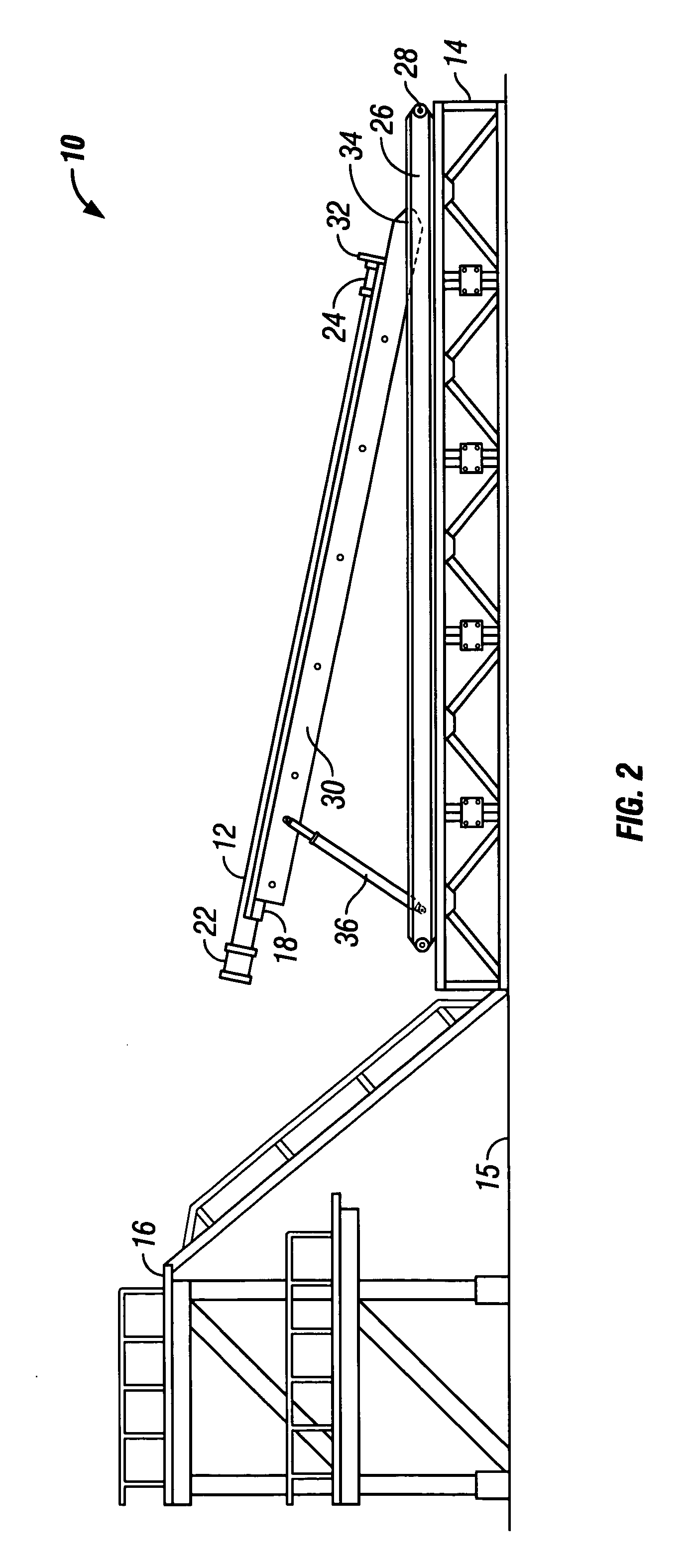
[0013]Referring now to the drawings and, more particularly, to FIG. 1, FIG. 2, FIG. 3, and FIG. 4, there is shown a series of elevational views of a presently preferred embodiment of pipe handling system 10 during operation. System 10 gently guides pipe 12, which may be a very large diameter pipe such as surface casing, or drill pipe, or any other type of pipe, from catwalk 14. Catwalk 14, as used herein may refer to any other platform or lower location which leads up to rig floor 16. Rig floor 16, as used herein, may be a drilling rig floor, workover rig floor, derrick floor, pipe storage location, or any other location which is generally elevated with respect to a lower position, such as 14 catwalk, the pipe rack, or other pipe storage locations. A rig may be an offshore rig, workover rig, drilling rig, and the like, for working with well bores. Special apparatus for placing pipe 12 onto moveable trough 18 or removing pipe 12 from moveable trough 18 to / from another location such a...


PUM


Abstract

A pick-up and lay-down pipe handling system and method provides a telescopingly extendable pipe trough which is telescopingly extendable from a lift frame. The lift frame is preferably pivotally moveable with respect to a support. A tilting mechanism is operable for tilting the pipe trough to either lateral side for unloading and / or loading purposes. A lift frame with slidable powered lift heads is provided to raise and lower pipes from a pipe rack to the pipe trough. A pivotal guide member on the slidable powered lift head to pivot into a guiding position for guiding pipe from the lift frame onto the pipe trough.

Description

TECHNICAL FIELD[0001]The present invention relates generally to apparatus and methods operable for automatically lifting and lowering oilfield tubulars and, more particularly, is especially suitable for lifting large diameter tubulars of heavy weight or other tubulars which are especially prone to lateral impact and friction damage during transport due to their significant weight.BACKGROUND ART[0002]Prior art oil field pipe handling systems and methods are well known for lifting and lowering drill pipe and casing to and from pipe racks, to and from the catwalk, and then onto the rig floor, and / or for stacking the pipe at other locations adjacent to or separated from the rig floor. However, the prior art systems have problems relating to damage of the tubulars during this process. Moreover, prior art systems are limited in their adaptability to the path of transportation typically to and from each particular rig floor, catwalk, and pipe rack arrangement.[0003]Numerous U.S. Patents sh...

Claims


Application Information

Patent Timeline
Patent Type & Authority Patents(United States)
IPC IPC(8): E21B19/00E21B19/15
CPCE21B19/155
Inventor HAWKINS, III, SAMUEL P.
Owner FRANKS INT
Learn More