
Setting device

a technology of a setting device and a holder, which is applied in the direction of paper/cardboard containers, containers, container making machinery, etc., can solve the problems of occupying a large space and a large number of structural components of the arrangement mentioned above, and achieve the effect of comfortable operation

Active Publication Date: 2006-02-07
HILTI AG
View PDF10 Cites 32 Cited by
  • Summary
  • Abstract
  • Description
  • Claims
  • Application Information

AI Technical Summary

Benefits of technology

The present invention is a setting device for fastening elements that aims to improve operational comfort. The device includes a blocking member that can be actuated by the locking element and moved from its releasing position into its blocking position. This reduces the number of functional parts and decreases the pressing force, making comfortable operation possible. Additionally, a control element can be guided and acted upon elastically by a spring element, making it compact and easy to control. The device also includes a coulisse device that ensures reliable functioning and a low-maintenance variant for easy maintenance. Overall, the invention provides a more comfortable and efficient setting device for fastening elements.

Problems solved by technology

However, it is disadvantageous that the arrangements mentioned above have a large number of structural component parts and take up a large amount of space.

Method used


Image

  • Setting device
  • Setting device
  • Setting device

Examples


Embodiment Construction

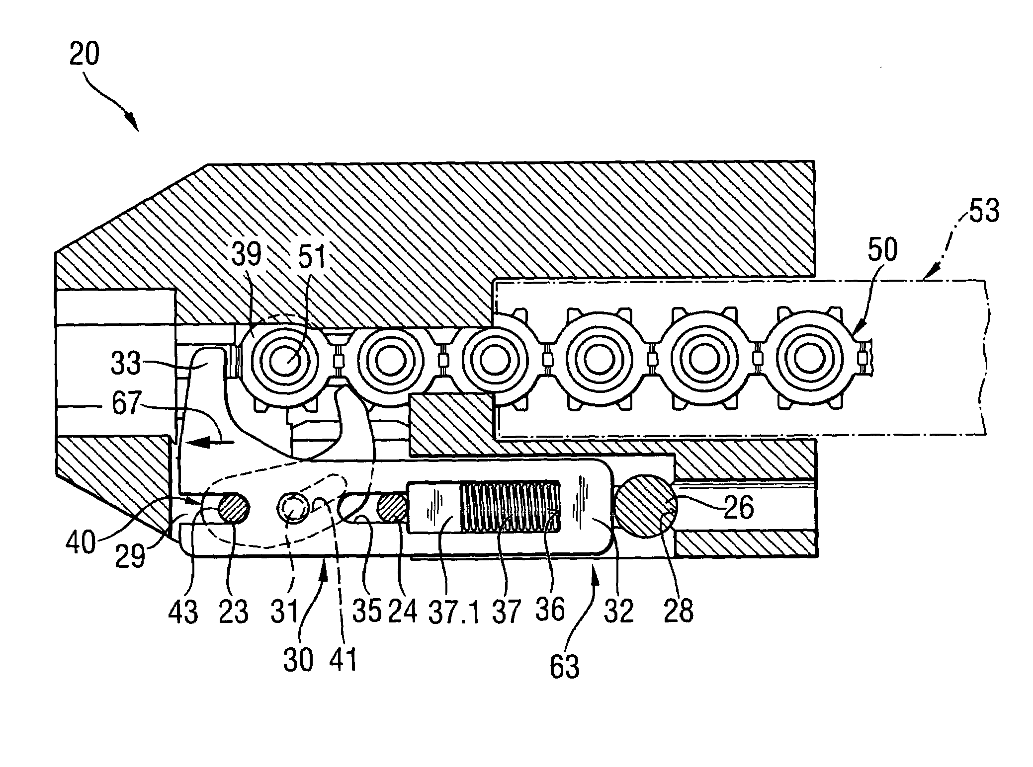
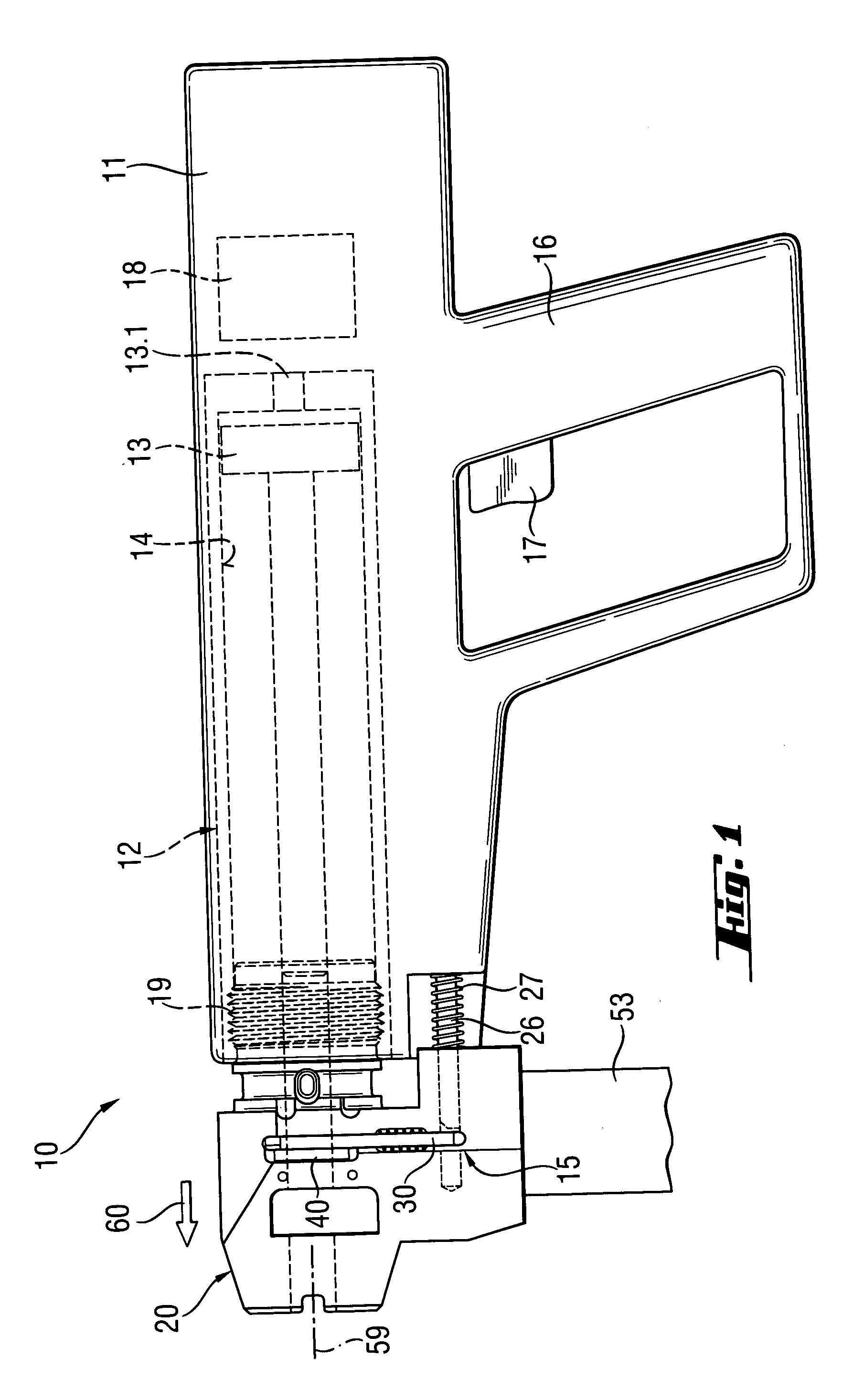
[0025]FIGS. 1 to 8 show a combustion-operated, hand-held setting device 10 by way of example. The setting device 10 has a setting mechanism 12 which is arranged in an axially extending housing 11 with a leading end and a trailing end comprising one or more parts and which has an axially extending setting piston 13 that is guided so as to be displaceable in a piston guide 14 for driving fastening elements 51 into a receiving material indicated in dashes in FIG. 1. A trigger 17 is arranged in a handle 16 of the setting device 10 for initiating a setting process by means of a firing unit 18 for a propellant charge inserted in a cartridge holder 13.1 of the setting mechanism 12.

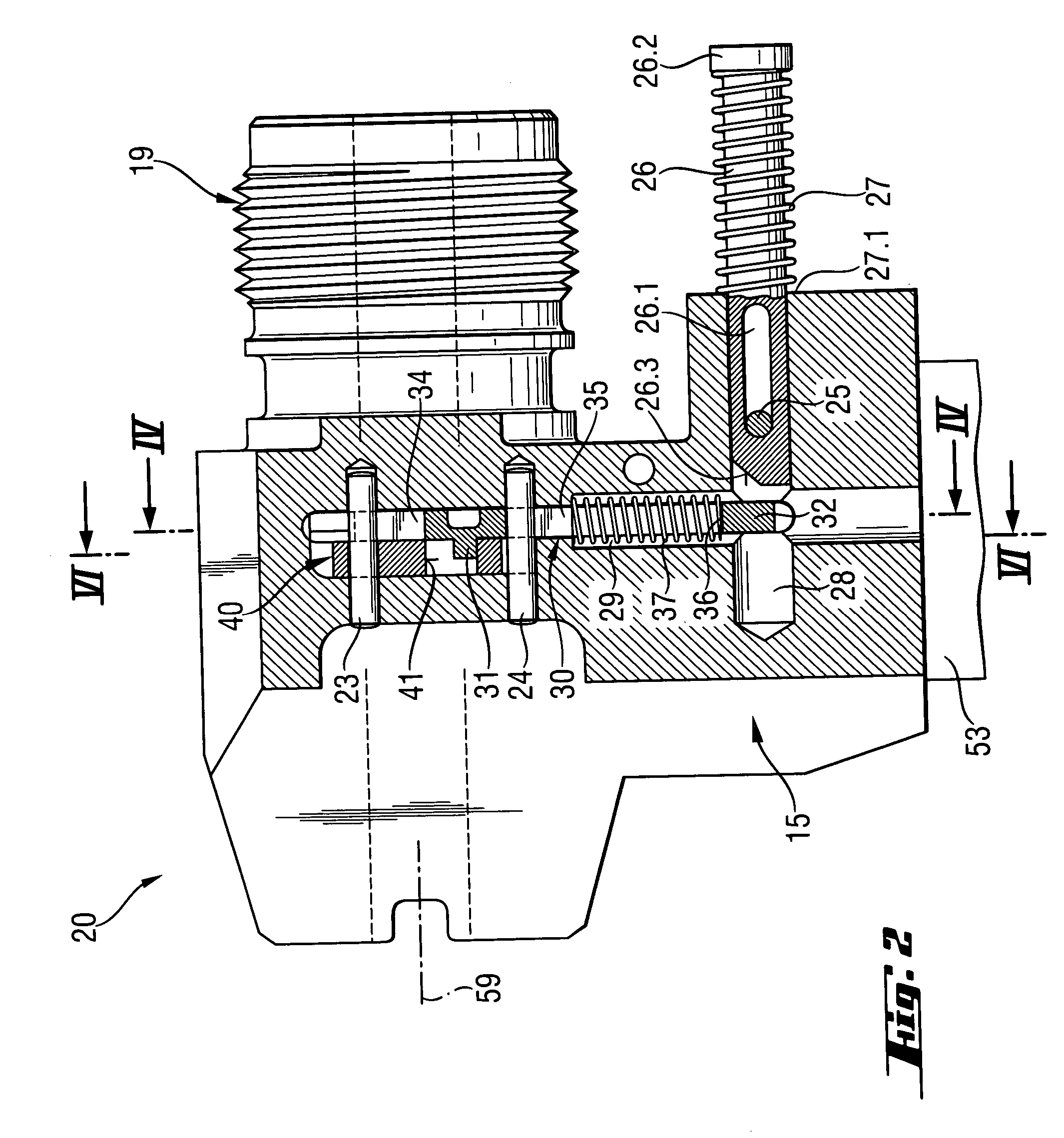
[0026]A muzzle part 20 adjoining the setting mechanism 12 (see especially FIG. 1) is arranged at the setting device 10 at the leading end of the housing 11 in setting direction 60. This muzzle part 20 is connected to the rest of the setting mechanism in the interior of the housing 11, by means of a threaded conne...


PUM

PropertyMeasurementUnit
displacementaaaaaaaaaa
axial displacementaaaaaaaaaa
distanceaaaaaaaaaa

Abstract

A setting device (10) for driving fastening elements into a receiving material has a housing (11), with a muzzle part (20) which is displaceable axially relative to the housing (11) and is arranged with a guide channel (38) for a fastening element strip (50) and opens into a receiving space (39) for a fastening element (51) to be driven in. Further, a locking element (30) is arranged in the muzzle part (20). The locking element (30) has a feeler portion (33) for detecting a fastening element (51) in the receiving space (39) and a locking part (32) for blocking the displacement of the muzzle part (20) relative to the housing (11) in a locking position (61) when a fastening element (51) is not detected in the receiving space (39) by the feeler portion (33). A blocking member (40) in the muzzle part (20) is movable into the guide channel (38) so as to block the fastening element strip (50). To improve a setting device (10) of this type, the blocking member (40) is in an operative connection with the locking element (30) so that the blocking member (40) can be actuated by the locking element (40).

Description

BACKGROUND OF THE INVENTION[0001]1. Field of the Invention[0002]The present invention is directed to a setting device for driving fastening elements into a receiving material. Setting devices of this kind can be operated with solid, gaseous or liquid combustible materials or also with compressed air. In combustion-operated setting devices, a setting piston is driven by means of the high-pressure combustion gases. Fastening elements can then be driven into a receiving material by means of the setting piston.[0003]2. Description of the Prior Art[0004]It is known from DE 40 32 200 C2 to provide a setting device with a muzzle part which is displaceable axially relative to a housing of the setting device and which has a receiving space for a fastening element that is to be driven into a receiving material. Further, a contact-pressing feeler is arranged at the setting device and allows a driving-in process when it is displaced relative to the muzzle part when the setting device is pressed...

Claims


Application Information

Patent Timeline
Patent Type & Authority Patents(United States)
IPC IPC(8): B21J15/28B25C1/14B25C1/18
CPCB25C1/184
Inventor JAKOB, ROBERTWEIBEL, MICHAEL
Owner HILTI AG
Learn More