
Toroidal type continuously variable transmission

a technology of continuously variable transmission and toroidal type, which is applied in the direction of friction gearings, gearing elements, gearings, etc., can solve the problems of increasing the cost required for assembling work and the increase of the manufacturing cost of the toroidal type continuously variable transmission

Inactive Publication Date: 2006-01-31
NSK LTD
View PDF34 Cites 273 Cited by
  • Summary
  • Abstract
  • Description
  • Claims
  • Application Information

AI Technical Summary

Benefits of technology

The invention is a toroidal type continuously variable transmission that allows for easy incorporation of balls into a ball spline. The transmission includes a rotating shaft, two discs, trunnions, displacement shafts, power rollers, a hydraulic pressing unit, a preload spring, and a ball spline. The first disc is supported around the rotating shaft and can rotate independently of the second disc. The trunnions are provided between the first and second discs and can swing around pivot shafts. The displacement shafts project from the inner side surfaces of the trunnions. The power rollers are sandwiched between the inner side surfaces of the two discs and can rotate on the displacement shafts. The hydraulic pressing unit is provided between the rotating shaft and the first disc and can press the first disc towards the second disc. The preload spring is provided between the rotating shaft and the first disc and can press the first disc even when the pressing unit is not operated. The ball spline supports the first disc and can rotate in sync with the rotating shaft. The invention allows for easy incorporation of balls into the ball spline without compressing the preload spring.

Problems solved by technology

Accordingly, the manufacturing cost of the toroidal type continuously variable transmission increases.
Thus, cost required for the assembling work is increased undesirably.

Method used


Image

  • Toroidal type continuously variable transmission
  • Toroidal type continuously variable transmission
  • Toroidal type continuously variable transmission

Examples


Embodiment Construction

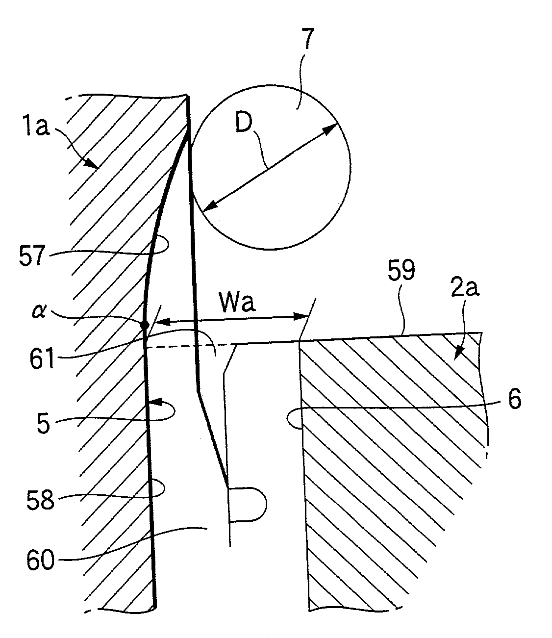
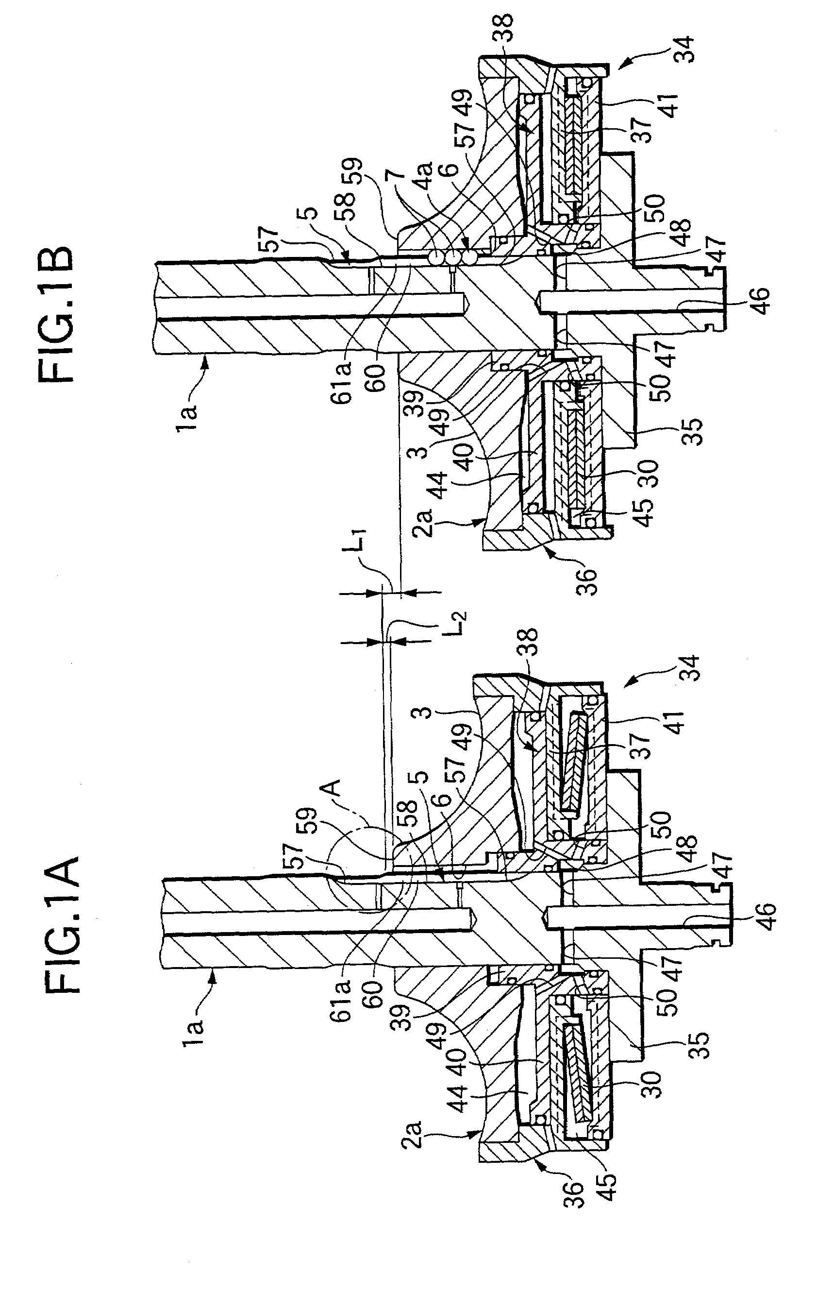
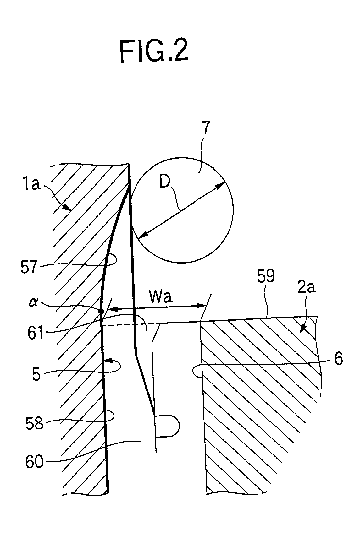
[0053]FIGS. 1A and 1B and FIG. 2 show an embodiment of the invention. Incidentally, this embodiment has a feature in that the dimensions of a first spline groove 5 formed in the outer circumferential surface of the forward end portion of an input-side rotating shaft 1a which is a rotating shaft is regulated by the relationship to an input-side disc 2a which is a first disc, when the work of inserting balls 7 and 7 between the first spline groove 5 and a second spline groove 6 formed in the inner circumferential surface of the input-side disc 2a is to be made easy. The configurations and operations of the other members are similar to those in the structure shown in FIG. 4. Therefore, illustration and description about those equivalent members will be omitted or simplified, and characteristic portions of the invention will be described chiefly below.

[0054]As shown in FIG. 1A, constituent members of a hydraulic pressing unit 34 assembled in advance in order to assemble a toroidal type ...


PUM


Abstract

A toroidal type continuously variable transmission having first and second discs supported around a rotating shaft and receiving power rollers therebetween includes a ball spline having a first spline groove formed in an outer circumferential surface of the rotating shaft, a second spline groove formed in an inner circumferential surface of the first disc, and balls provided between the first spline groove and the second spline groove rollably. An axial position of an end portion of an effective groove portion of the first spline groove is located to correspond to an axial position of an inner end portion of the second spline groove or more closely to the second disc than the axial position thereof when a pressing unit, a preload spring and the first disc are installed around the rotating shaft, pressure oil is not fed to the pressing unit, and the preload spring is not elastically deformed.

Description

BACKGROUND OF THE INVENTION[0001]1. Field of the Invention[0002]The present invention relates to a toroidal type continuously variable transmission, which is used as a transmission unit constituting an automobile automatic transmission unit or as a transmission for regulating the running speed of various industrial machines such as a pump.[0003]2. Description of the Related Art[0004]Toroidal type continuously variable transmissions have been known as a kind of transmission unit constituting an automobile transmission. Some toroidal type continuously variable transmissions have been put into practical use. Such toroidal type continuously variable transmissions already put into practical use are heretofore known well as disclosed in a large number of official gazettes such as U.S. Pat. No. 5,033,322, U.S. Pat. No. 5,569,112 and U.S. Pat. No. 5,651,750. A basic structure of such a toroidal type continuously variable transmission will be described with reference to FIG. 3. The structure...

Claims


Application Information

Patent Timeline
Patent Type & Authority Patents(United States)
IPC IPC(8): F16H15/38F16H61/662
CPCF16H61/6649F16H15/38
Inventor KOBAYASHI, NORIHISAMIYATA, SHINJIIMANISHI, TAKASHIHASHITANI, HIDEKI
Owner NSK LTD
Learn More