
Method for dimensioning a riser element with integrated auxiliary lines

a technology of auxiliary lines and risers, which is applied in the direction of sealing/packing, drilling pipes, and well accessories, etc., can solve the problems of lower flexural stiffness than the equivalent all-steel tubes for the same working, and the use of clamps can be incompatible with the use of floats on the risers, so as to prevent buckling of tubes

Active Publication Date: 2006-01-31
INST FR DU PETROLE
View PDF4 Cites 33 Cited by
  • Summary
  • Abstract
  • Description
  • Claims
  • Application Information

AI Technical Summary

Benefits of technology

The present invention aims to prevent buckling of the tubes that constrain the auxiliary lines while maintaining the riser's architecture. The invention provides a method for dimensioning the riser by considering the pressure difference between the internal and external pressure applied to the tubular elements. The method takes into account the stresses undergone by the tubular elements and the main tube when the tubular elements experience a difference in pressure. The method also includes determining the relative elongation of the tubular elements and the main tube when the tubular elements undergo a difference in pressure. The invention provides a sliding pivot link that allows a longitudinal play in relation to the main tube, and the tubular elements can be hooped by reinforcing wires made of glass fibers, carbon fibers, or aramid fibers coated in a polymer matrix.

Problems solved by technology

However, the drawback of hooped tubes is that they have a lower flexural stiffness than the equivalent all-steel tubes for the same working pressure.
However, the use of clamps can be incompatible with the use of floats on the riser.

Method used


Image

  • Method for dimensioning a riser element with integrated auxiliary lines
  • Method for dimensioning a riser element with integrated auxiliary lines
  • Method for dimensioning a riser element with integrated auxiliary lines

Examples


Embodiment Construction

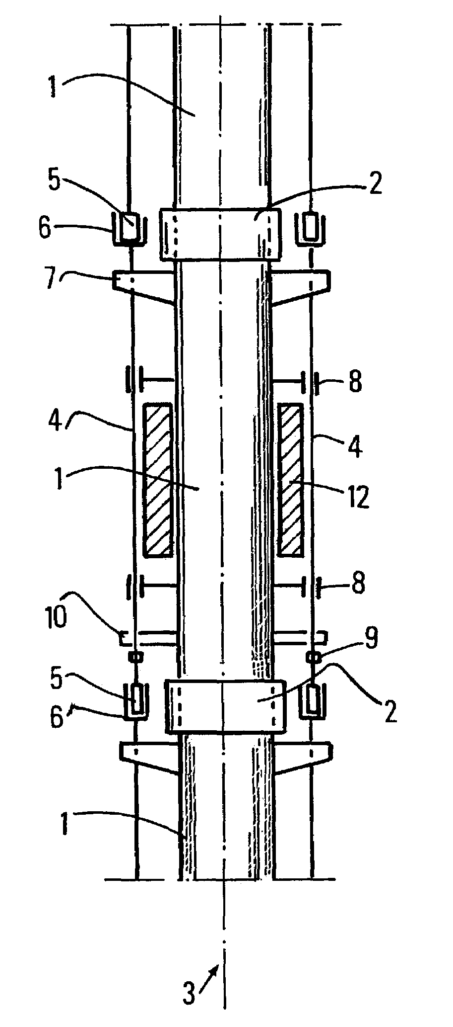
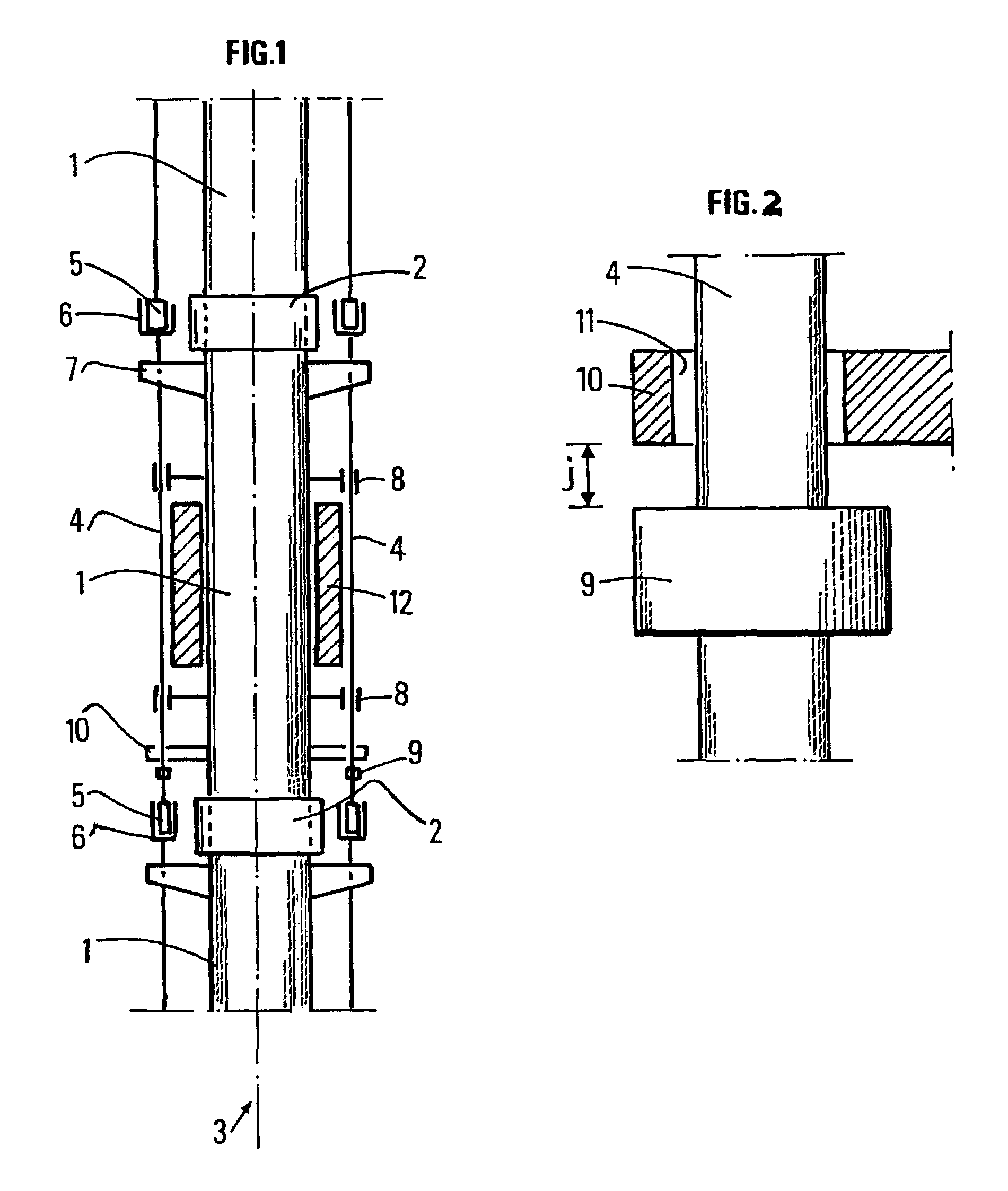
[0020]FIG. 1 diagrammatically shows a part of a riser. Reference number 1 designates an element of the main tube of the riser. Elements 1 are tubular and assembled together by mechanical connectors 2 which can be those described in document EP-0,147,321. The assembly of elements 1 forms the main tube of axis 3. Two auxiliary lines are shown in FIG. 1. The auxiliary lines conventionally referred to as kill line and choke line are used to ensure the safety of the well during show control procedures in the well. The auxiliary lines are arranged parallel to axis 3. The auxiliary lines consist of the assembly of elements 4 whose length is substantially equal to the length of elements 1. Thus, two elements 4 arranged at the same height on the riser correspond to each element 1. Elements 4 are also tubular. Each element 4 comprises at its ends male and female terminal pieces bearing reference numbers 5 and 6 respectively. The terminal pieces of an element 4 cooperate with the terminal piec...


PUM


Abstract

The method relates to a riser comprising a main tube and auxiliary lines. Each tubular element forming the auxiliary lines is fastened at one end by a complete link with the central tube and at the other end by a link allowing a longitudinal play J with the central tube.The method provides adjustment of play J so that, on the one hand, during conventional drilling operations, the elements forming the auxiliary lines slide in relation to the central tube and, on the other hand, during show control or testing operations, the elements forming the auxiliary lines form hyperstatic assemblies with the central tube.The method thus allows to prevent buckling of the peripheral lines when they are under pressure because they work under hyperstatic conditions.

Description

FIELD OF THE INVENTION[0001]The present invention relates to risers comprising a main tube provided with peripheral lines. It provides a method of determining the longitudinal play between the peripheral line and the main tube so that the peripheral line is in a hyperstatic situation in a predetermined operating mode, in particular when it is subjected to high internal pressures.[0002]A riser consists of an assembly of tubular elements whose length ranges between 15 and 25 m (50 and 80 feet) assembled by connectors. The tubular elements constitute, on the one hand, the main tube which contains the drillpipe and in which the drilling mud circulates, and on the other hand the auxiliary lines known as kill line and choke line, arranged parallel to the main tube, which allow circulation of a fluid between the blowout preventers at the riser bottom and the top of the central riser without flowing through the main tube.BACKGROUND OF THE INVENTION[0003]In the prior art, auxiliary lines con...

Claims


Application Information

Patent Timeline
Patent Type & Authority Patents(United States)
IPC IPC(8): E21B29/12E21B17/01
CPCE21B17/01F16L39/04
Inventor GUESNON, JEANGAILLARD, CHRISTIAN
Owner INST FR DU PETROLE
Learn More