Missile interceptor

a technology of missile interceptor and missile, which is applied in the direction of launching weapons, instruments, transportation and packaging, etc., can solve the problems of missiles colliding by a number of miles, enemy nations, and different speed,

Inactive Publication Date: 2006-01-31
BOYD JOSEPH J
View PDF2 Cites 12 Cited by
  • Summary
  • Abstract
  • Description
  • Claims
  • Application Information

AI Technical Summary

Benefits of technology

[0014]These methods are a complete change of values where the one shot deal of “one bullet hitting another”, is replaced by a slow, absolute kill as the interceptor overtakes the ICBM from the rear. Since the anti-missiles are still in the area of other missiles, they can systematically seek them out and destroy them.

Problems solved by technology

A great danger to America from an enemy nation is the intercontinental ballistic missile (ICBM).
Yet, the missiles may have a difference in speed of 30,000 mph, and thus the slightest error in the trajectory or the timing can cause the missiles to miss colliding by a number of miles.
They are still vulnerable to our late launched anti-ballistic missiles clear down to the time they reach the reentry stage.
The system works, but it has problems and requires a large number of anti-ballistic missiles to be on ready.
The greatest problem with the front interceptor system is the great difference in relative speed between the interceptor and the missile.
At the last second, correction is impossible.

Method used


Image

  • Missile interceptor
  • Missile interceptor
  • Missile interceptor

Examples


Embodiment Construction

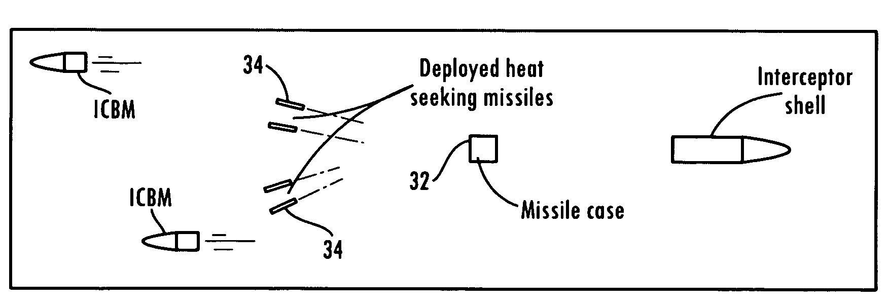
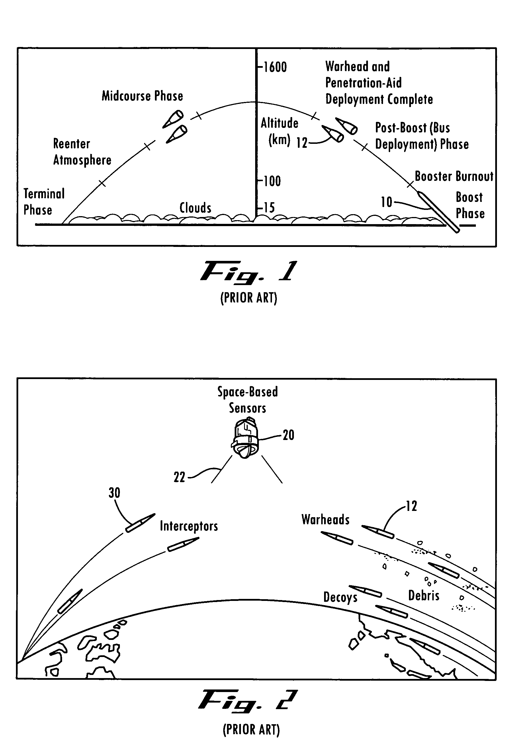
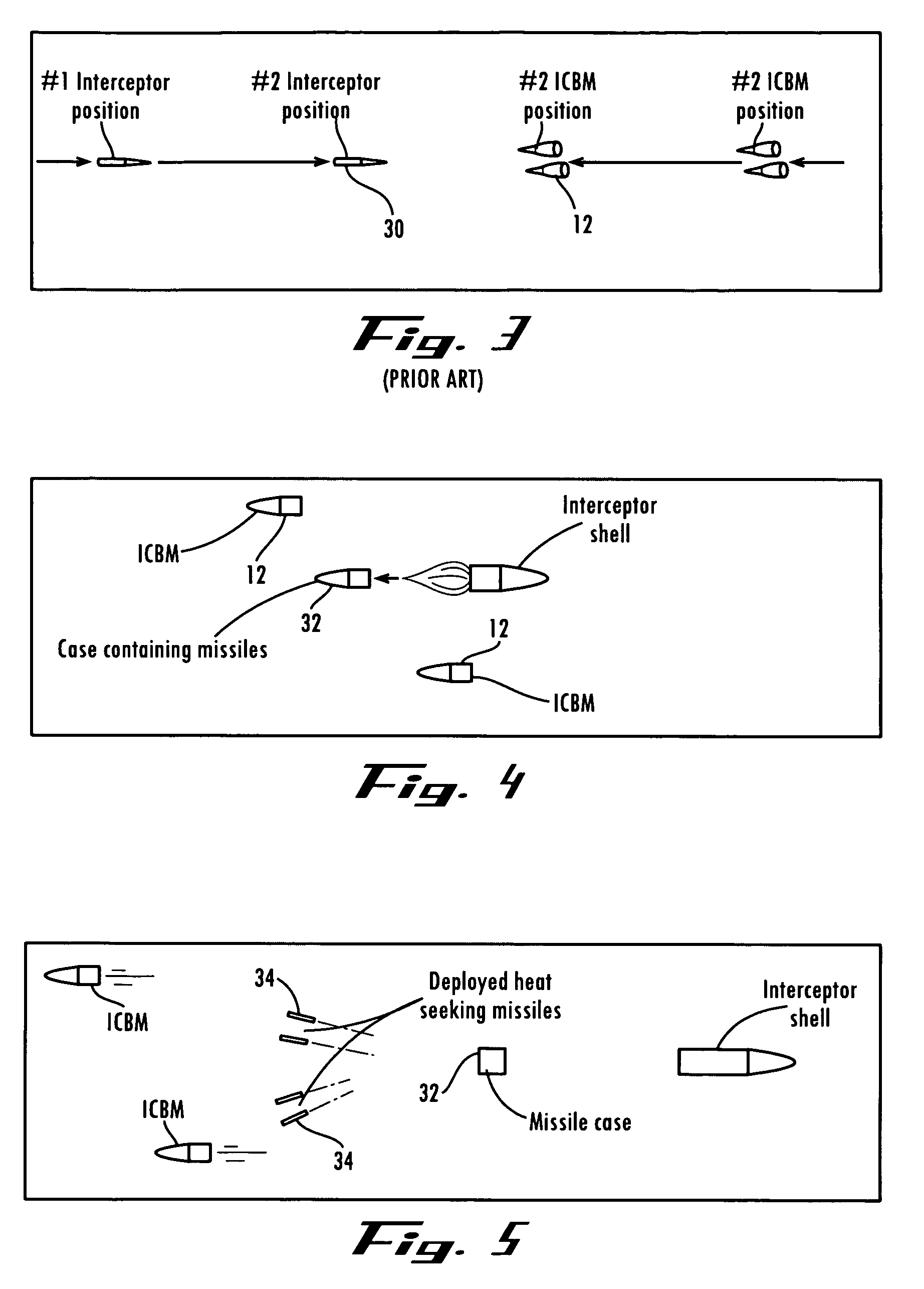
[0022]Referring now in detail to the drawing figures, wherein like reference numerals represent like parts throughout the several views, FIG. 1 illustrates the phases of a typical enemy ballistic missile trajectory. In the boost phase, the enemy launches a rocket driven first flying device, or missile 10, and its payload up above the atmosphere. The post-boost phase occurs next, where the multiple warheads 12 and penetration aids are released from the boost missile. Next, during the mid-course phase, the missiles travel a long distance on trajectories above the atmosphere, and on the terminal phase, they reenter the atmosphere to zero in on their targets.

[0023]FIG. 2 shows our conventional response to the threat of the enemies ICBM. The space-based sensors 20 first warn of the attack, and then continuously track all objects from launch to the end, and they also use high energy lasers 22 to destroy the booster and the post-boost missiles. In the mid-course flight, if the interceptors...


PUM


Abstract

The present invention is a method of interception. When a missile is launched and detected by a satellite, an anti-missile rocket is launched to intercept it. When the anti-missile rocket nears the point of interception, it goes into a turn of about 180 degrees, to reverse its course, and comes in behind the enemy missile, at a speed almost equal to that of the ICBM. In this maneuver, coming in behind the ICBM, it reduces the relative speed of the two rockets from about 13,000 mph to about 50 mph, and allows the interceptor missile to approach the ICBM at a slow speed and easily destroy it.

Description

BACKGROUND OF THE INVENTION[0001]1. Field of the Invention[0002]The present invention generally is a means for intercepting and destroying intercontinental, cruise and shorter range missiles.[0003]2. Description of the Related Art[0004]A great danger to America from an enemy nation is the intercontinental ballistic missile (ICBM). If these missiles carry nuclear warheads, and are able to penetrate our defense system, they can destroy city after city with but little effort on the enemies' part. These missiles are very effective and efficient. They are ballistic in that they are guided and propelled during the initial phase of the flight, and follow a free-falling ballistic trajectory towards the target under the influence of gravity the remainder of the distance. Initially, they are propelled high above the atmosphere by rockets and may divide into many separate warheads that are freely moving missiles on their own and that are destined for different targets.[0005]Our present system ...

Claims


Application Information

Patent Timeline
Patent Type & Authority Patents(United States)
IPC IPC(8): B64D1/04
CPCF42B15/12
Inventor BOYD, JOSEPH J.
Owner BOYD JOSEPH J
Why Eureka
Try Eureka