Method and apparatus for forming and displaying projection image from a plurality of sectional images

a technology of projection image and sectional image, applied in image enhancement, tomography, instruments, etc., can solve the problem of inferior method in terms of separative display of internal organs

Inactive Publication Date: 2006-01-24
HITACHI LTD
View PDF21 Cites 17 Cited by
  • Summary
  • Abstract
  • Description
  • Claims
  • Application Information

AI Technical Summary

Benefits of technology

[0011]Memories are provided so as to correspond to the pixel values respectively. A sum of values in identical pixel positions of the memories is obtained. Desired weighting is applied to the sum. Data obtained by the weighting are displayed as projection images on the monitor screen. Accordingly, there are obtained projection images which are excellent in separate display of portion of object to be examined such as internal organs, etc., in sectional images and in which respective portions are separated sharply.

Problems solved by technology

The maximum value projecting and displaying method, however, had a problem that the method was inferior in terms of separative display of internal organs because nothing but a projection image based on the maximum value of density was displayed.
On the other hand, as shown in FIG. 21, the integrated value projecting and displaying method had a problem that the shadow of an internal organ d2 which is small in the distance of passage of projection line L was buried under the shadow of an internal organ d1 which is large in the distance of passage of projection line L because the shadow of the small internal organ d2 was thinner than the shadow of the large internal organ d1, etc.

Method used


Image

  • Method and apparatus for forming and displaying projection image from a plurality of sectional images
  • Method and apparatus for forming and displaying projection image from a plurality of sectional images
  • Method and apparatus for forming and displaying projection image from a plurality of sectional images

Examples


second embodiment

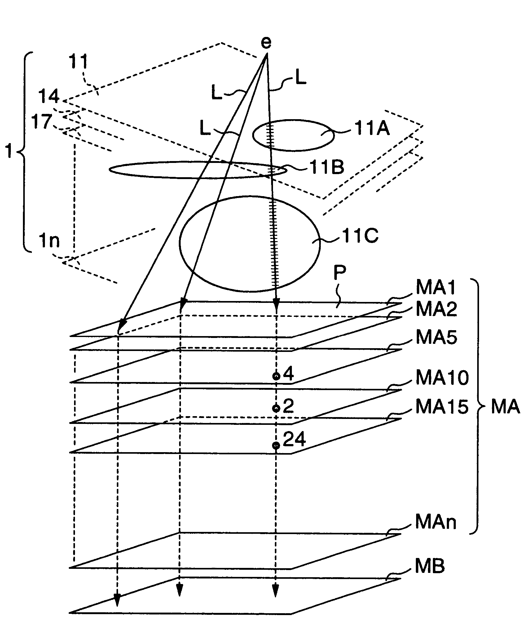
[0066]FIG. 4 is an explanatory view of the projection image forming and displaying method. In FIG. 4, parts the same as or equivalent to those in FIG. 1 are referenced correspondingly.

[0067]MC1 to MCn are CT value marking bit memories which are provided separately by CT value. MC1 is a first CT value marking bit memory; MC2 is a second CT value marking bit memory; . . . MCn is an n-th CT value marking bit memory. Assuming now that the first CT value is the CT value of 1 and the n-th CT value is the CT value of 1000, the first CT value marking bit memory MC1 is a bit memory for marking the CT value of 1, the second CT value marking bit memory MC2 is a bit memory for marking the CT value of 2, and the n-th CT value marking bit memory MCn is a bit memory for marking the CT value of 1000.

[0068]The CT values corresponding to the respective numbers of the CT value marking bit memories MC1 to MCn are set suitably in accordance with the number of used CT value marking bit memories, the CT v...

first embodiment

[0086]If the counting process is carried out in accordance with the CT values on the basis of the first embodiment shown in FIGS. 1 through 3, portions or internal organs of each CT value can be displayed separately or emphatically when weighting coefficients are set separately by CT value. With respect to the method of setting the weighting coefficients, as shown in FIG. 7A, when a weighting coefficient curve 72 with the CT value as the abscissa axis and with the weighting coefficient as the ordinate axis is modified while being displayed, setting of arbitrary weighting with respect to each CT value can be performed. Specifically, three kinds of weighting coefficient curves set in advance are registered in a memory. When one of three weighting coefficient curve selection buttons 73a, 73b and 73c displayed is pointed by the cursor so as to be selected, a weighting coefficient curve 72 corresponding to the button is displayed as shown by the curve 72 in FIG. 7A.

[0087]To correct the w...


PUM


Abstract

The virtual three-dimensional image of an observed object is formed by arranging a plurality of sectional images and projected from a viewpoint fixed to a predetermined position onto a projection plane which is fixed to a predetermined position to form and display a perspective image. The pixel value on the sectional image which is transversed by a projection line extending from the viewpoint to the projection plane are read and, if the read value coincides with one of a plurality of predetermined values, pixel data are recorded in a pixel recording region corresponding to that value in pixel value memories. While the projection line scans the pixels one by one on the projection plane, for each coming scanned pixel the pixel data are recorded. After all the data are recorded, the pixel data recorded in the pixel value memories are read out and the data are displayed on a display as a perspective image.

Description

CROSS-REFERENCE TO RELATED APPLICATIONS[0001]This application is a continuation of application Ser. No. 09 / 284,081 filed on Apr. 7, 1999 which is a 371 of PCT / JP97 / 03174, filed Sep. 9, 1997 now abandoned. The contents of application Ser. No. 09 / 284,081 are hereby incorporated herein by reference in their entirety.TECHNICAL FIELD[0002]The present invention relates to a projection image forming and displaying method and apparatus for obtaining a projection image on the basis of a plurality of sectional images from a medical image system, such as an X-ray CT system, an MRI system, an ultrasonic tomograph system, or the like, by which sectional images can be obtained.BACKGROUND ART[0003]Conventionally, as methods of this type, there are known a maximum value projecting and displaying method, an integrated value projecting and displaying method, etc., as shown in the following papers (1) and (2).[0004](1) P. J. Keller, B. P. Drayer, E. K. Fram, K. D. Williams, C. L. Dumoulin, S. P. Souza...

Claims


Application Information

Patent Timeline
Patent Type & Authority Patents(United States)
IPC IPC(8): G06K9/00A61B6/03G06T11/00G06T17/00
CPCG06T11/001G06T17/00G06T15/08G06T2207/30004
Inventor GOTO, YOSHIHIRO
Owner HITACHI LTD
Why Eureka
Try Eureka