
Interference mitigation in a wireless communication system

a wireless communication system and interference mitigation technology, applied in the field of communication systems, can solve the problems of interference from other transmissions in the utilized spectrum, affecting the success of data communication, and unlicensed internet access transmissions being subject to interference from other transmissions

Active Publication Date: 2006-01-24
CISCO TECH INC
View PDF26 Cites 107 Cited by
  • Summary
  • Abstract
  • Description
  • Claims
  • Application Information

AI Technical Summary

Benefits of technology

[0013]By virtue of one embodiment of the present invention, dynamic signal to noise ratio measurements made on received signals are used to identify degraded segments of a channel. The degraded segments are then no longer used for transmitting payload data. In the context of an orthogonal frequency division multiplexing (OFDM) communication system, degraded OFDM subchannels, as determined on a real-time basis, are not used to transmit payload data. In an OFDM network where access is shared in the time domain among multiple transmitters and a single allocable time slot includes an integer number of OFDM bursts, the medium access control layer adjusts packet length, and therefore the amount of data to be included in a given slot, in response to the fluctuating number of available subchannels.

Problems solved by technology

One detriment to successful data communication is the presence of other transmissions in the utilized spectrum.
However, wireless data transmissions there may be subject to interference from incumbent narrowband analog video transmissions.
Another band slated for broadband wireless Internet access is the U-NII (Unlicensed National Information Infrastructure) band at 5.725–5.85 GHz, but the unlicensed Internet access transmissions there are subject to interference from other such transmissions as well as other services entitled to access to the band.
Aside from spectrally overlapping unwanted signals, there is also self-interference resulting from signal reflections between the transmitter and receiver.
The disadvantage of this approach is that link capacity used to incorporate redundancy reduces the payload data carrying capacity.
Furthermore, the redundant data is typically spread across the entire channel even though the interference may be limited to a rather narrow segment.
The network modifications adopted in response to the measured interference increase deployment costs and / or reduce network capacity.
Furthermore, the long-term characteristics of the channel cannot be predicted based on measurements made at the time of deployment.
Interference may change frequency and location, even in real-time, rendering modifications made at deployment time essentially useless.

Method used


Image

  • Interference mitigation in a wireless communication system
  • Interference mitigation in a wireless communication system
  • Interference mitigation in a wireless communication system

Examples


Embodiment Construction

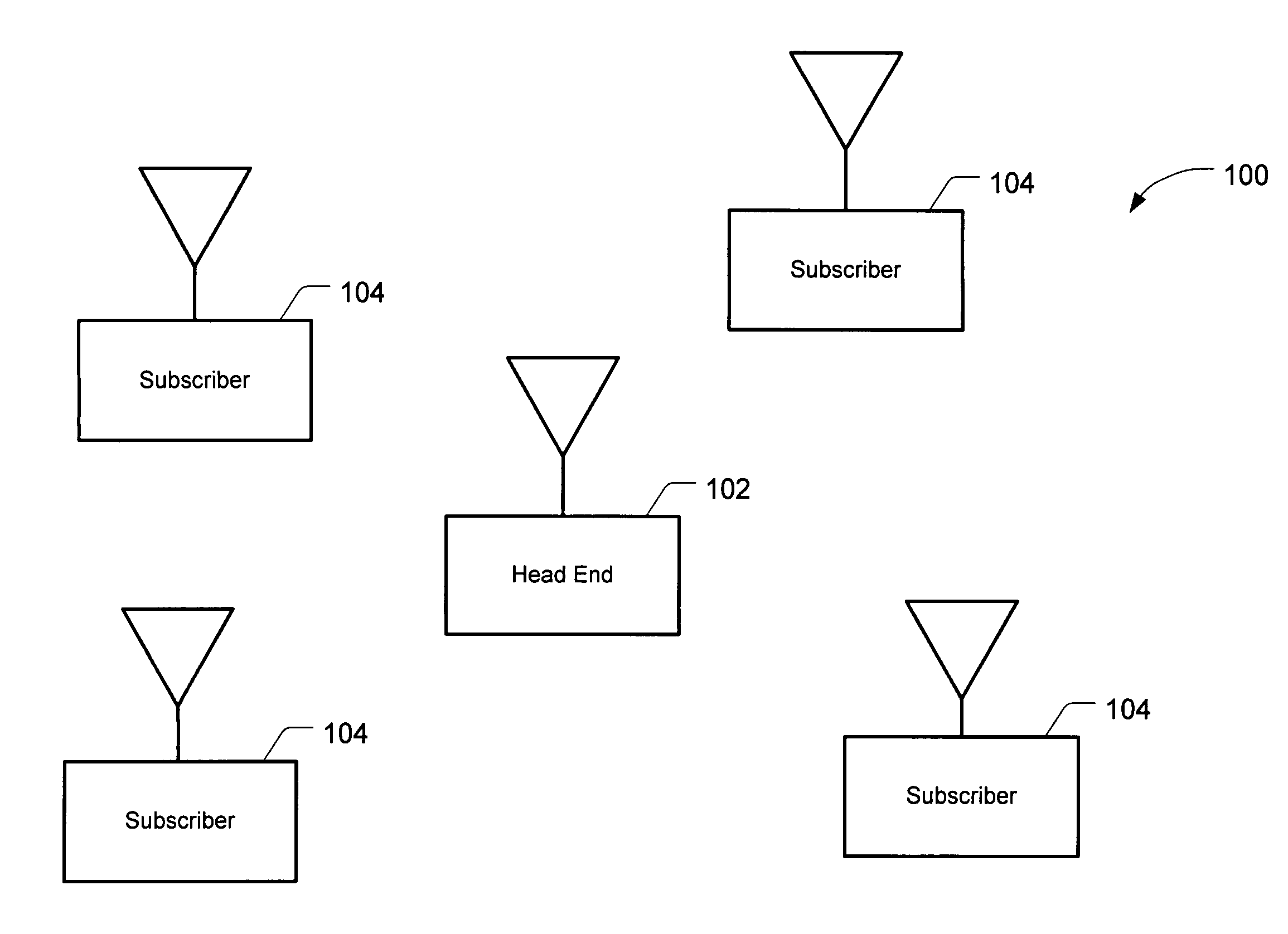
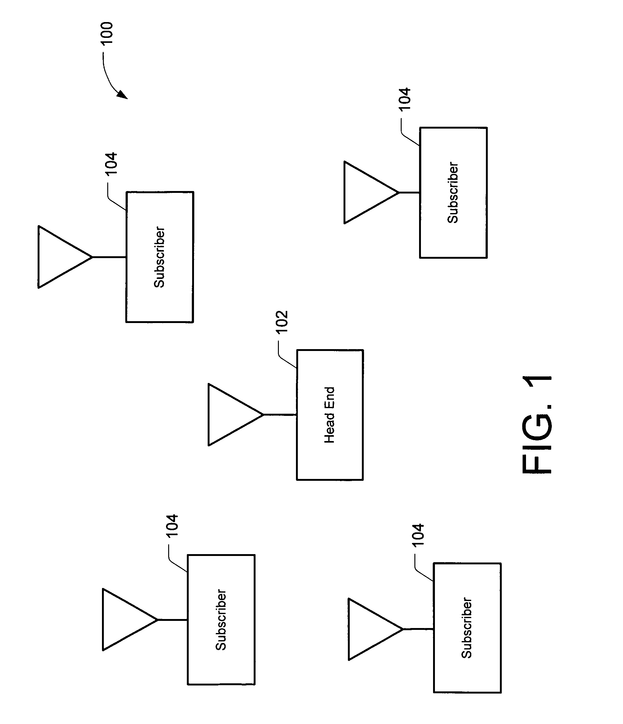
[0025]FIG. 1 depicts a point to multipoint wireless communication network 100 suitable for implementing one embodiment of the present invention. The present invention is, however, not limited to wireless networks. Network 100 includes a central access point or head end 102 and multiple subscriber units 104. All communication is typically either to or from central access point 102. Communication from central access point 102 to one or more of subscriber units 104 is herein referred to as downstream communication. Communication from any one of subscriber units 104 to central access point 102 is herein referred to as upstream communication. In one embodiment, different frequencies are allocated to upstream and downstream communication. This is referred to as frequency division duplexing (FDD). Alternatively, time division duplexing (TDD) may be employed where upstream and downstream communications share the same frequencies. Although the point to multipoint network is used to describe ...


PUM


Abstract

By virtue of one embodiment of the present invention, dynamic signal to noise ratio measurements made on received signals are used to identify degraded segments of a channel. The degraded segments are then no longer used for transmitting payload data. In the context of an orthogonal frequency division multiplexing (OFDM) communication system, degraded OFDM subchannels, as determined on a real-time basis, are not used to transmit payload data. In an OFDM network where access is shared in the time domain among multiple transmitters and a single allocable time slot includes an integer number of OFDM bursts, the medium access control layer adjusts packet length, and therefore the amount of data to be included in a given slot, in response to the fluctuating number of available subchannels.

Description

STATEMENT OF RELATED APPLICATIONS[0001]The present invention is related to the subject matter of the following U.S. patent applications:[0002]U.S. patent application Ser. No. 09 / 234,929 entitled, “IMPROVED OFDM CHANNEL IDENTIFICATION” filed Jan. 21, 1999, now U.S. Pat. No. 6,611,551.[0003]U.S. patent application Ser. No. 09 / 234,629 entitled, “SYSTEM FOR INTERFERENCE CANCELLATION” filed Jan. 21, 1999, now U.S. Pat. No. 6,442,130.[0004]U.S. patent application Ser. No. 09 / 410,945 entitled, “OFDM CHANNEL ESTIMATION IN THE PRESENCE OF INTERFERENCE” filed Oct. 4, 1999, now U.S. Pat. No. 6,487,253.[0005]U.S. patent application Ser. No. 09 / 419,444 entitled “DECODING DATA FROM MULTIPLE SOURCES”, filed Oct. 15, 1999, now U.S. Pat. No. 6,654,921.BACKGROUND OF THE INVENTION[0006]The present invention relates to communications systems, and more particularly to broadband communication systems.[0007]A point to multipoint wireless communication system represents a potentially effective solution to ...

Claims


Application Information

Patent Timeline
Patent Type & Authority Patents(United States)
IPC IPC(8): H04J11/00H04B7/212H04L12/26
CPCH04L5/023H04L27/2608H04L5/0044
Inventor ANIKHINDI, SANTOSHBOTTERILL, IAIN
Owner CISCO TECH INC
Learn More