
Grouted tilting patient positioning table for vascular applications

a patient positioning and patient technology, applied in the field of patient positioning platforms, can solve the problems of inability to properly position patients on patient positioning platforms, inability to properly position patients, and many current patient positioning platforms lack flexibility to accommodate emerging situations

Inactive Publication Date: 2006-01-17
GE MEDICAL SYST GLOBAL TECH CO LLC
View PDF68 Cites 95 Cited by
  • Summary
  • Abstract
  • Description
  • Claims
  • Application Information

AI Technical Summary

Benefits of technology

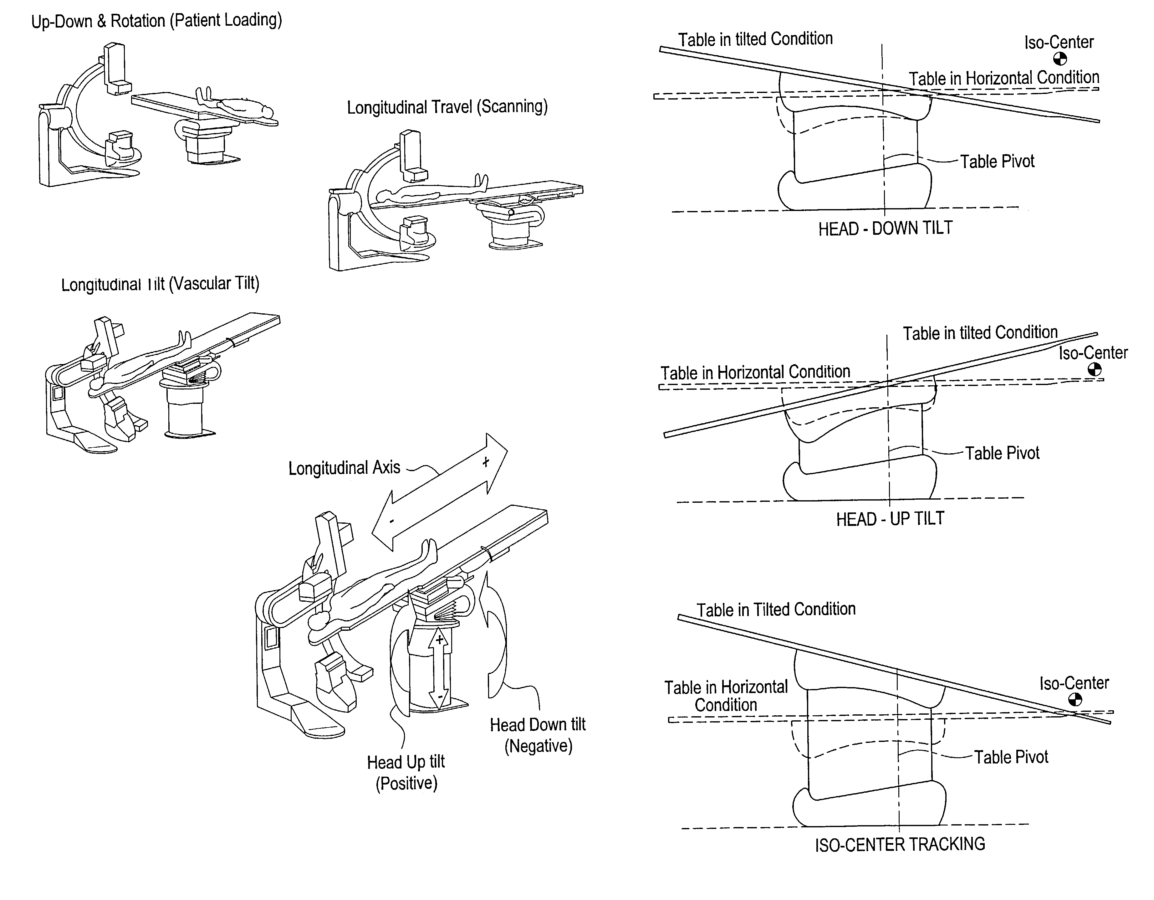
[0007]Certain embodiments include a system and method for positioning a patient with a patient positioning system. The system includes a patient positioning surface for supporting a patient. The system also includes a lift subsystem for adjusting elevation of the patient positioning surface, a longitudinal subsystem for moving the patient positioning surface in a longitudinal direction, a lateral subsystem for moving the patient positioning surface in a lateral direction, a tilt subsystem for tilting the patient positioning surface, and a rotation subsystem for rotating the patient positioning surface. The system further includes a control subsystem for controlling operation of the patient positioning system. The control subsystem may also avoid collision with the ground and / or predetermined objects.
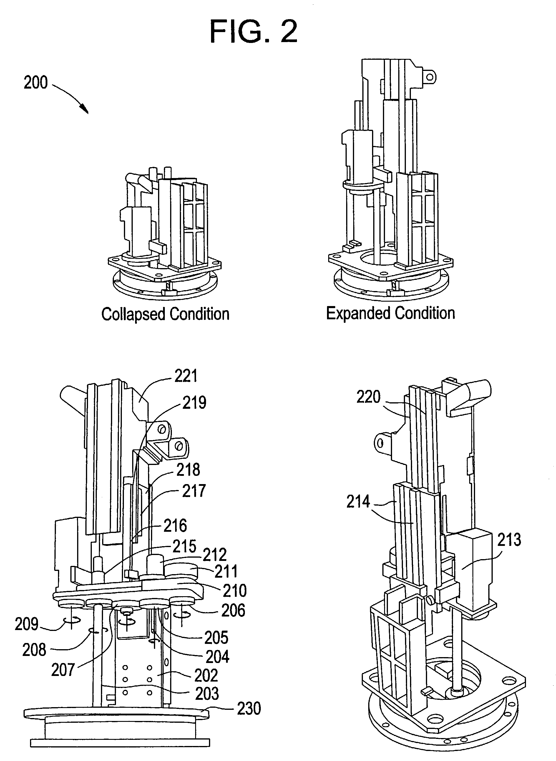
[0008]In a certain embodiment, the control subsystem performs iso-center tracking to maintain a region of interest of the patient in an image area during tilt. The lift subsystem adjusts elevation of the patient positioning surface using a two-stage synchronized telescopic lift system. The longitudinal subsystem moves the patient positioning surface in a longitudinal direction using a two-stage synchronized telescopic longitudinal system. The longitudinal and lateral subsystems allow manual or motorized movement of the patient positioning surface in lateral direction and / or longitudinal direction.
[0009]The system may also include a base affixed to a floor for securing the patient positioning system. The system may also include patient restraints for securing the patient to the patient positioning surface. The system may also include a power-on brake for braking when a voltage is supplied to the power-on brake and a power-off brake for braking when a voltage is removed from the power-off brake. The system may further include at least one encoder for determining the position of the patient positioning surface. The encoder may allow the patient positioning surface to return to a recorded position.

Problems solved by technology

Current patient positioner platforms may introduce limitations in obtaining images of blood flow in arteries, heart, lungs, or brain, for example.
Currently, patient positioner platforms possess limitations in properly positioning a patient for vascular applications, such as emergent situations, venous access, and CO2 studies.
Additionally, many current patient positioner platforms lack flexibility to accommodate emergent situations, venous access, and CO2 studies of a patient.

Method used


Image

  • Grouted tilting patient positioning table for vascular applications
  • Grouted tilting patient positioning table for vascular applications
  • Grouted tilting patient positioning table for vascular applications

Examples


Embodiment Construction

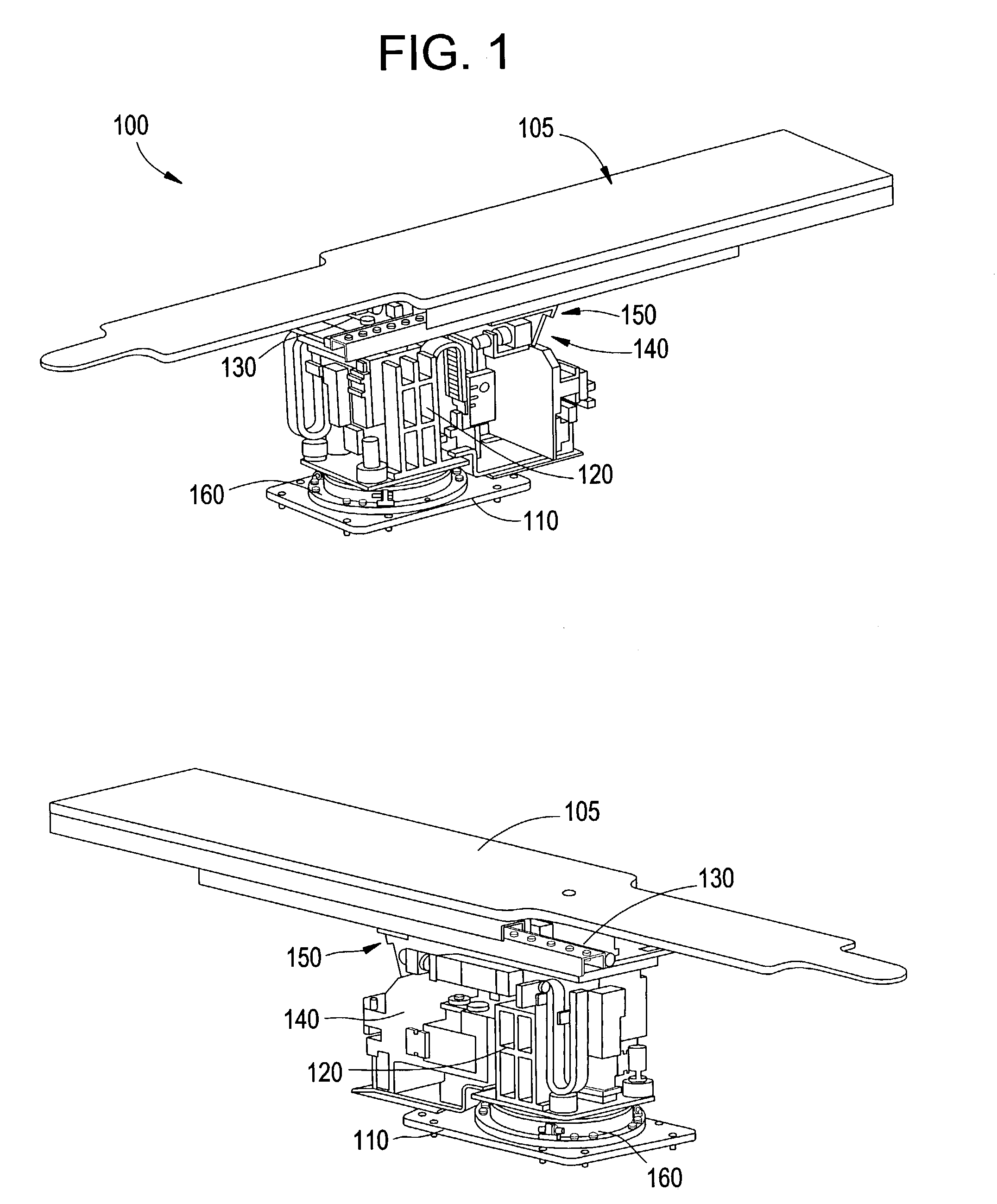
[0024]FIG. 1 illustrates a patient positioning system 100 that is used in accordance with an embodiment of the present invention. The patient positioning system 100 includes a patient positioning surface 105, a base 10, a telescopic lift system 120, a longitudinal system 130, a tilt system 140, a lateral system 150 and a rotation system 160. The patient positioning system 100 is grouted, or fixed to the floor at the table base 110.

[0025]To enhance loading and unloading of a patient, the patient positioning surface 105 may rotate around a vertical axis using the rotation system 160. The patient positioning surface 105 may also be manually rotated about the rotation system 160. To move the patient to an image area, the patient positioning surface 105 may move vertically using the telescopic lift system 120 from a height at which the patient may be conveniently loaded to a height where imaging may occur (780 mm to 1080 mm, for example). To move a portion of the patient's body into the ...


PUM


Abstract

Certain embodiments include a system and method for positioning a patient with a patient positioning system. The system includes a patient positioning surface for supporting a patient. The system also includes a lift subsystem for adjusting elevation of the patient positioning surface, a longitudinal subsystem for moving the patient positioning surface in a longitudinal direction, a lateral subsystem for moving the patient positioning surface in a lateral direction, a tilt subsystem for tilting the patient positioning surface, and a rotation subsystem for rotating the patient positioning surface. The system further includes a control subsystem for controlling operation of the patient positioning system and a base affixed to a floor for securing the patient positioning system. The control subsystem may perform iso-center tracking to maintain a region of interest of the patient in an image area during tilt. The control subsystem may also avoid collision with the ground and / or predetermined objects.

Description

BACKGROUND OF INVENTION[0001]The present invention generally relates to a patient positioning platform. In particular, the present invention relates to a patient positioning platform with particular use in vascular applications.[0002]Patient positioner platforms allow a medical practitioner, such as a doctor, nurse or technician, to position a patient during a medical procedure, such as XR, CT, EBT, nuclear, and PET procedures. Patient positioner platforms, such as tables or other supports, allow a patient to be elevated, moved in lateral & longitudinal directions, rotated and / or tilted during a procedure. Patient positioning platforms improve a medical practitioner's ability to examine and / or perform a medical procedure on a patient.[0003]There is a need for an improved patient positioning platform that may be used in angiography, neurology, and cardiac procedures. Current patient positioner platforms may introduce limitations in obtaining images of blood flow in arteries, heart, l...

Claims


Application Information

Patent Timeline
IPC IPC(8): A61G13/04A61B6/04A61G13/06A61N5/10A61G13/02
CPCA61B6/0457A61G13/06A61G13/04A61B6/0487
Inventor VARADHARAJULU, MUTHUVELANNARAYANASAMY, RAJAGOPALSOMASUNDARAM, BASKARALAKKAT, SHAJI
Owner GE MEDICAL SYST GLOBAL TECH CO LLC
Learn More