
Depth and puncture control for blood vessel hemostasis system

a technology of depth and puncture control and blood vessel hemostasis, which is applied in the field of blood vessel puncture site closure systems and methods, can solve the problems of inability to accurately place the absorbable material plug directly over the puncture site, unsuitable for patients with substantial amounts, and high risk of hematoma, and achieve the effect of inhibiting blood loss

Inactive Publication Date: 2006-01-10
BOSTON SCI CORP +11
View PDF221 Cites 101 Cited by
  • Summary
  • Abstract
  • Description
  • Claims
  • Application Information

AI Technical Summary

Benefits of technology

This system effectively inhibits bleeding and promotes hemostasis by accurately positioning the pledget outside the blood vessel, preventing thrombosis and allowing for safe reaccess to the puncture site without compromising blood flow.

Problems solved by technology

In addition, a risk of hematoma exists since bleeding from the vessel may continue beneath the skin until sufficient clotting effects hemostasis.
Further, external pressure to close the vascular puncture site works best when the vessel is close to the skin surface and may be unsuitable for patients with substantial amounts of subcutaneous adipose tissue since the skin surface may be a considerable distance from the vascular puncture site.
The application of an absorbable material such as collagen or a non-absorbable tissue adhesive at the puncture site has several drawbacks including: 1) possible injection of the material into the blood vessel causing thrombosis; 2) a lack of pressure directly on the blood vessel puncture which may allow blood to escape beneath the material plug into the surrounding tissue; and 3) the inability to accurately place the absorbable material plug directly over the puncture site.
The use of an anchor and plug system addresses these problems to some extent but provides other problems including: 1) complex and difficult application; 2) partial occlusion of the blood vessel by the anchor when placed properly; and 3) complete blockage of the blood vessel or a branch of the blood vessel by the anchor if placed improperly.
Another problem with the anchor and plug system involves reaccess.
Reaccess of a particular blood vessel site sealed with an anchor and plug system is not possible until the anchor has been completely absorbed because the anchor could be dislodged into the blood stream by an attempt to reaccess.
When these conventional cannulas are advanced into the access tract, the cannulas often encounter scar or muscular tissue that requires substantial force to advance the cannula through these layers.
Accordingly, the sealing plug may not be accurately placed over the puncture site.
It has been observed, however, that in some circumstances blood flashing out the proximal end of the device does not form blood drops as readily as would be desired.
These factors can conspire to make the resulting bleed-back signal challenging to interpret and less meaningful to the casual observer.
Additionally, blood running onto the handle is messy and may undesirably wet the user's gloves.

Method used


Image

  • Depth and puncture control for blood vessel hemostasis system
  • Depth and puncture control for blood vessel hemostasis system
  • Depth and puncture control for blood vessel hemostasis system

Examples


Embodiment Construction

[0053]Referring to the drawing figures, like reference numerals designate identical or corresponding elements throughout the several figures.

[0054]In the context of the present invention, “pledget” means a piece of sponge formed into a generally elongated shape having a size which allows delivery in a hydrated state through a delivery cannula or introducer to a site of a puncture in a blood vessel.

[0055]“Sponge” means a biocompatible material which is capable of being hydrated and is resiliently compressible in a hydrated state. Preferably, the sponge is non-immunogenic and may be absorbable or non-absorbable.

[0056]“Absorbable sponge” means sponge which, when implanted within a human or other mammalian body, is absorbed or resorbed by the body.

[0057]“Hydrate” means to partially or fully saturate with a fluid, such as saline, water, contrast agent, thrombin, therapeutic agents, or the like.

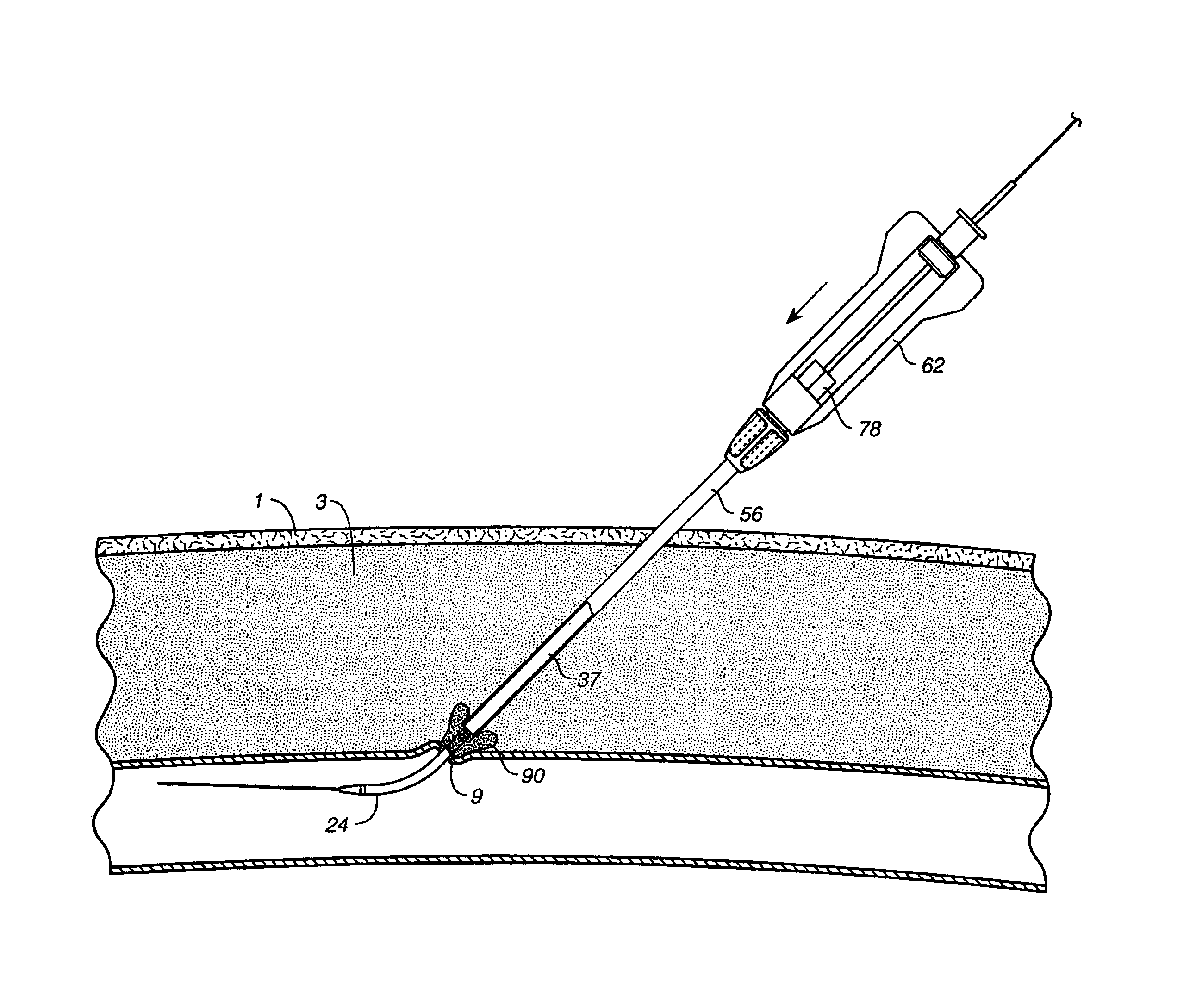
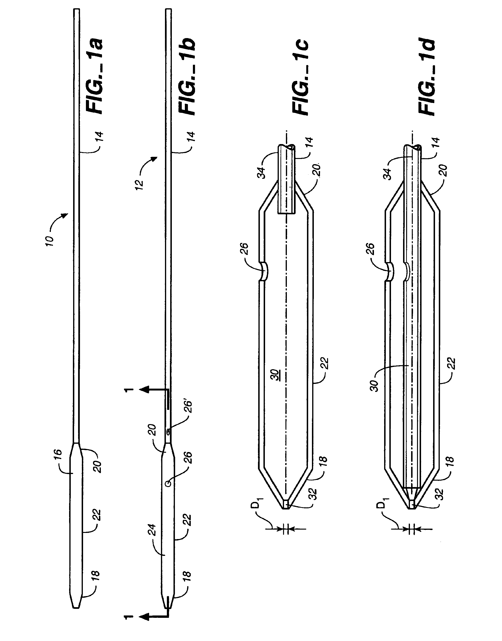
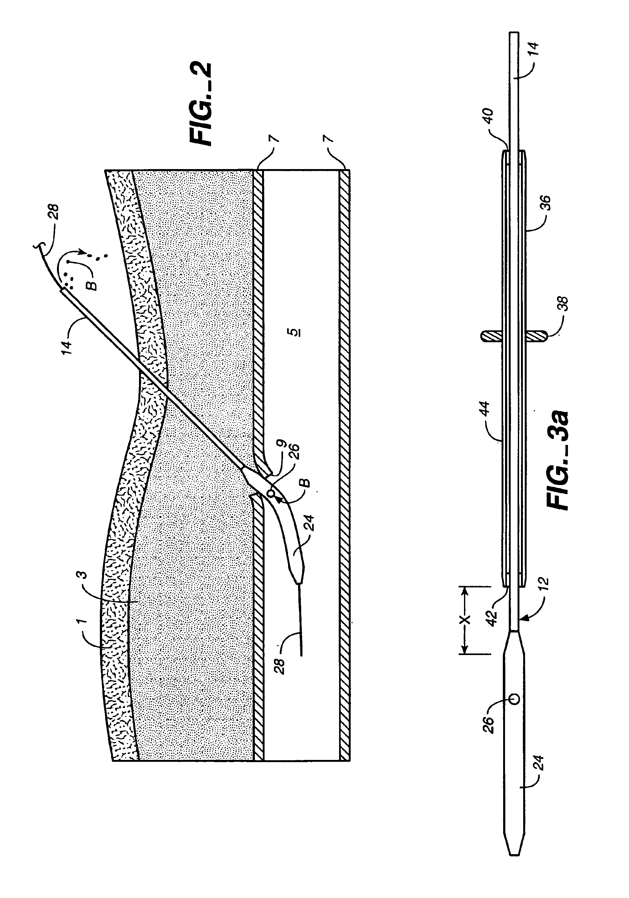
[0058]FIG. 1a illustrates a puncture control tip 10 in accordance with a first embodiment of th...


PUM


Abstract

A depth and puncture control system for a blood vessel hemostasis system includes a blood vessel puncture control tip which, when positioned in the lumen of a blood vessel, can inhibit the flow of blood out of the puncture site. When used together with a pledget delivery cannula and a pledget pusher, the control tip and the delivery catheter can both inhibit blood loss out the puncture site and inhibit the introduction of pledget material and tissue fragments into the blood vessel. The system also includes a handle which releasably connects together the control tip, pusher, and delivery cannula to permit limited longitudinal motion between the control tip and the delivery cannula, and between the pusher and the delivery cannula.

Description

[0001]This application is a continuation-in-part of U.S. application Ser. No. 09 / 621,670 filed Jul. 24, 2000, which is a continuation-in-part of U.S. application Ser. No. 09 / 613,439 filed Jul. 11, 2000, which is a division of U.S. application Ser. No. 09 / 071,284 filed May 1, 1998, now U.S. Pat. No. 6,162,192. This application also is a continuation-in-part of U.S. application Ser. No. 09 / 263,603 filed Mar. 5, 1999, now U.S. Pat. No. 6,315,753, which is a continuation-in-part of the '284 application. The '670 application claims the priority benefit under 35 USC §119(e) to U.S. provisional application Ser. No. 60 / 156,007 filed Sep. 23, 1999. The disclosures of the foregoing applications are incorporated herein by reference.BACKGROUND OF THE INVENTION[0002]1. Field of the Invention[0003]The invention relates to closure systems and methods for blood vessel puncture sites.[0004]2. Brief Description of the Related Art[0005]A large number of diagnostic and interventional procedures involve...

Claims


Application Information

Patent Timeline
Patent Type & Authority Patents(United States)
IPC IPC(8): A61F13/36A61B17/00A61B19/00
CPCA61B17/0057A61B2017/00637A61B2019/462A61B2017/00672A61B2017/00654A61B2090/062
Inventor ASHBY, MARKCRAGG, ANDREWURQUIDI, LUISCHI-SING, EDUARDOLEE, ERIC
Owner BOSTON SCI CORP
Learn More