
Folding multi-tool with adjustable pliers

a multi-tool and adjustable technology, applied in the field of multi-functional pocket tools, can solve the problems of limiting the amount of gripping force comfortably applied by the user, adding to the complexity of the tool, and opening the side of the channel-shaped handle outwardly, and achieve the effect of great gripping for

Inactive Publication Date: 2006-01-10
LEATHERMAN TOOL GROUP
View PDF58 Cites 36 Cited by
  • Summary
  • Abstract
  • Description
  • Claims
  • Application Information

AI Technical Summary

Benefits of technology

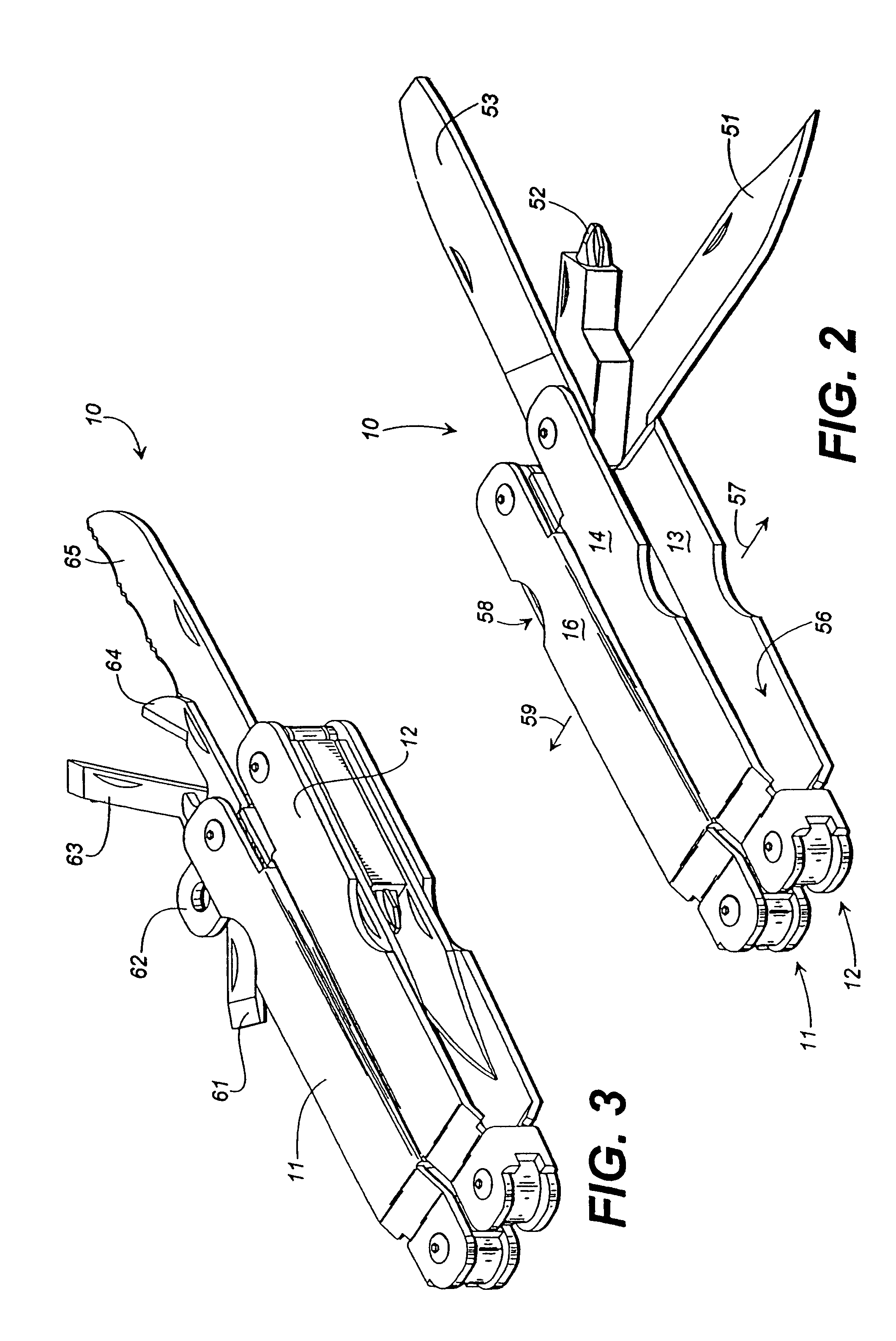
[0010]Preferably, the folding multi-tool includes, in each of the handles, at least one tool pivotally mounted to the second ends for pivotal movement between a closed position and an opened position, with the tools being received in the open sides of the handles. Preferably, the individual tools can be moved from the closed positions to the opened positions while the folding multi-tool is in its closed, compact configuration. Also preferably, the partly closed sides of the folding multi-tool are provided with rounded edges for greater comfort.
[0019]It is another object of the present invention to provide a folding multi-tool with a plurality of individual tools which can be easily and quickly deployed.

Problems solved by technology

One disadvantage of such known arrangements is that when using the pliers of the tool, the open sides of the channel-shaped handles face outwardly, away from one another.
When gripping the tool tightly to secure an object with the plier jaws, the open sides of the channel-shaped handles can become uncomfortable and can limit the amount of gripping force comfortably applied by the user.
This tends to add to the complexity of the tool and somewhat reduces the strength of the pliers.
Another disadvantage of such known arrangements is that to deploy an individual tool for use, the multi-function tool handles must be opened, the individual tool selected and opened, and the multi-function tool handles closed.
This is somewhat cumbersome and slow.

Method used


Image

  • Folding multi-tool with adjustable pliers
  • Folding multi-tool with adjustable pliers
  • Folding multi-tool with adjustable pliers

Examples


Embodiment Construction

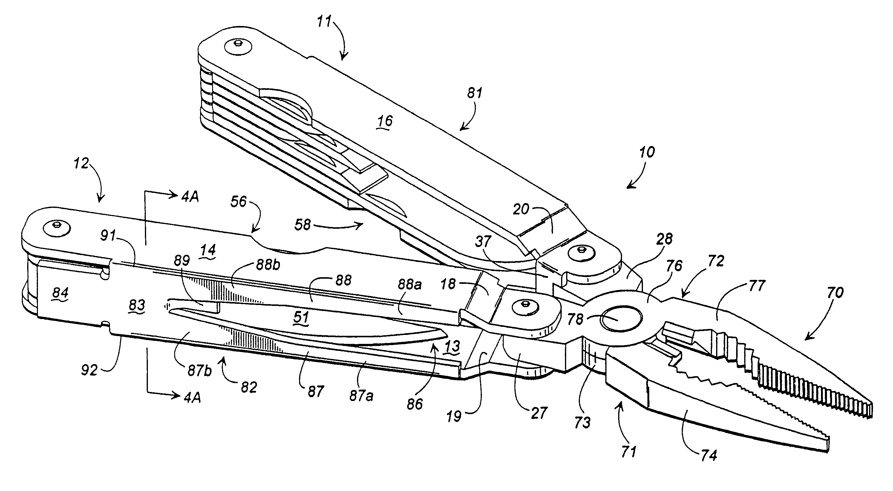
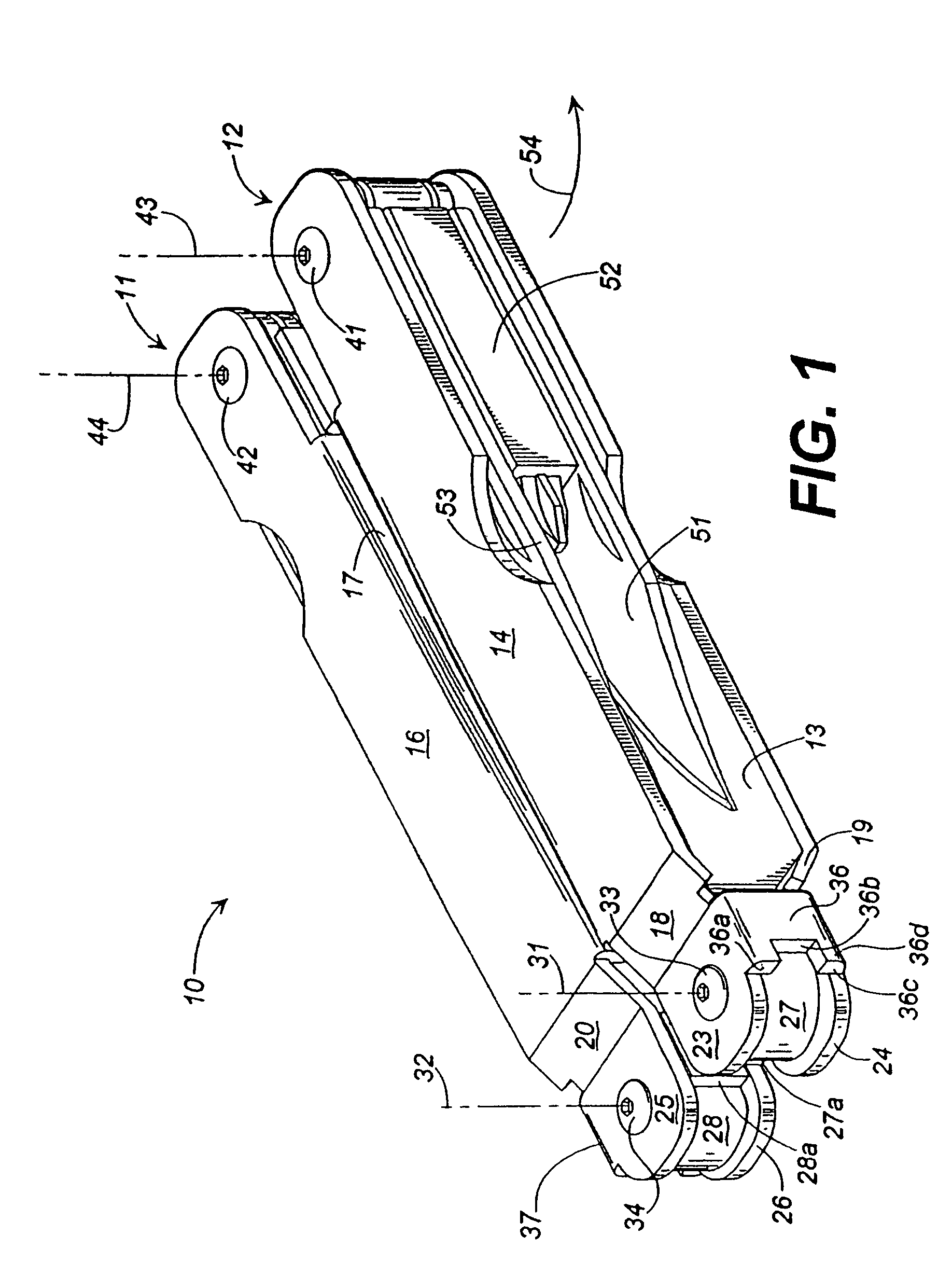
[0032]Referring now to the drawing figures, wherein like reference numerals represent like parts throughout the several views, FIG. 1 shows a folding multi-tool 10 according to a preferred form of the invention. The folding multi-tool 10 depicted in FIG. 1 is shown in a closed, compact configuration, such as would be used for storing the tool in a sheath. The folding multi-tool 10 includes first and second channel-shaped handles 11 and 12.

[0033]Each of the channel-shaped handles 1l and 12 is generally “C”-shaped in cross-section and includes an upper wall, a lower wall, and a vertically extending wall between the upper and lower walls. For example, handle 12 includes lower wall 13 and upper wall 14 and an unshown (at least in FIG. 1) vertical wall extending therebetween. Likewise, channel-shaped handle 11 includes an upper wall 16, an unshown lower wall, and a vertical wall 17 extending therebetween.

[0034]The channel-shaped handles include integral shoulders, such as shoulders 18, 1...


PUM


Abstract

A folding multi-tool comprising first and second generally channel-shaped handles each having first and second ends, each generally channel-shaped handle having an open side and an at least partly closed side opposite the open side, the at least partly closed sides comprising plier-receiving openings. The folding multi-tool also includes pliers including first and second plier halves pivotally and adjustably mounted to each other, with the plier halves being pivotally mounted between flanges at the first ends of the handles. Control straps extend between the flanges for limiting the maximum pivotal movement of the plier halves and for frictionally resisting pivotal movement of the plier halves. The folding multi-tool is foldable between a closed, compact configuration and an opened, extended configuration for operating the pliers and in the opened, extended configuration the open sides of the handles face each other.

Description

CROSS-REFERENCE TO RELATED APPLICATION[0001]This application is a continuation of application Ser. No. 10 / 218,848, filed Aug. 13, 2002 now U.S. Pat. No. 6,718,585, which is a continuation of application Ser. No. 09 / 859,344, filed May 16, 2001, now U.S. Pat. No. 6,430,768, which is a continuation of application Ser. No. 09 / 204,432, filed Dec. 3, 1998 now abandoned, which is a continuation of application Ser. No. 08 / 784,941, filed Jan. 16, 1997, now U.S. Pat. No. 6,047,426, which is a continuation-in-part of application Ser. No. 08 / 609,975, filed Feb. 29, 1996, now U.S. Pat. No. 5,697,114.TECHNICAL FIELD[0002]The present invention relates generally to a multi-function pocket tool which includes adjustable pliers and other selected tools.BACKGROUND OF THE INVENTION[0003]Multi-function tools are well known. In typical multi-function tools, pliers and other selected tools, such as screwdrivers, knife blades, files, etc., are provided in a single tool. Known multi-function tools often inc...

Claims


Application Information

Patent Timeline
IPC IPC(8): B25B7/22B25F1/00B26B11/00
CPCB26B11/003B25F1/003B25F1/04B25B7/10
Inventor MCINTOSH, HERMAN J.GRIFFEY, KEN E.COOK, GREG
Owner LEATHERMAN TOOL GROUP
Learn More