Eureka AIR delivers breakthrough ideas for toughest innovation challenges, trusted by R&D personnel around the world.

Self-tightening keyless chuck

a keyless chuck and self-tightening technology, applied in the field of keyless chucks, can solve the problems of loss of safety, loss of working efficiency, and loosening of the jaw on the tool, and achieve the effects of reducing the risk of loosening in operation, increasing the gripping force, and great gripping for

Inactive Publication Date: 2005-09-29
SHANXI HUIFENG POWER TOOLS
View PDF18 Cites 8 Cited by
  • Summary
  • Abstract
  • Description
  • Claims
  • Application Information

AI Technical Summary

Benefits of technology

[0006] To overcome the aforementioned disadvantages and drawbacks in the prior art, the present invention provides a safe and simple self-tightening keyless chuck, which has a locking function and improves the strength of a front sleeve and which is less susceptible to loosening when used for a percussive tool.

Problems solved by technology

A conventional keyed or keyless chuck has the disadvantage that because the nut and the jaw are secured only by rotation of threads, the jaw tends to loosen its grip on a tool due to axial percussive vibrations transmitted through the chuck and the tool during operation.
This will cause the tool to skid, thus resulting in a loss of working efficiency and a loss of safety.
If the grooves are too shallow, the chuck will have a poor anti-percussion performance.
This, however, will affect the efficiency of production and can result in an increase of defective products.
To overcome this drawback, it is necessary to provide a pressing machine with a higher pressing accuracy or larger tonnage, which however will increase the cost of production.
This configuration, however, is complicated in structure and manufacturing process, and the front sleeve of the chuck which has a low strength is susceptible to damage.

Method used


Image

  • Self-tightening keyless chuck
  • Self-tightening keyless chuck
  • Self-tightening keyless chuck

Examples


Embodiment Construction

[0040] A detailed description of the present invention is provided with reference to the drawings and embodiments below.

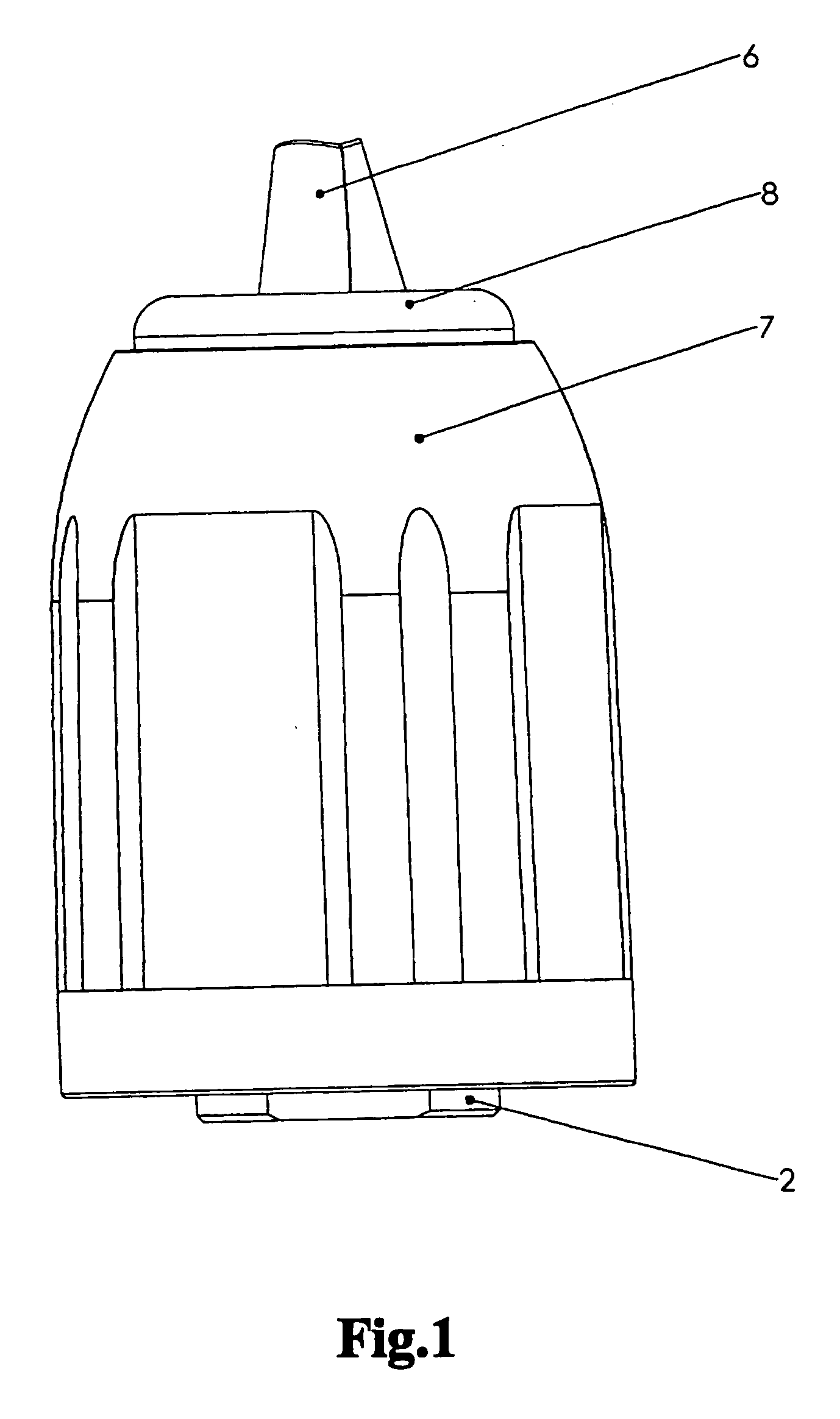
[0041]FIG. 1 is a front view of a keyless chuck manufactured according to the preferred embodiment of the present invention.

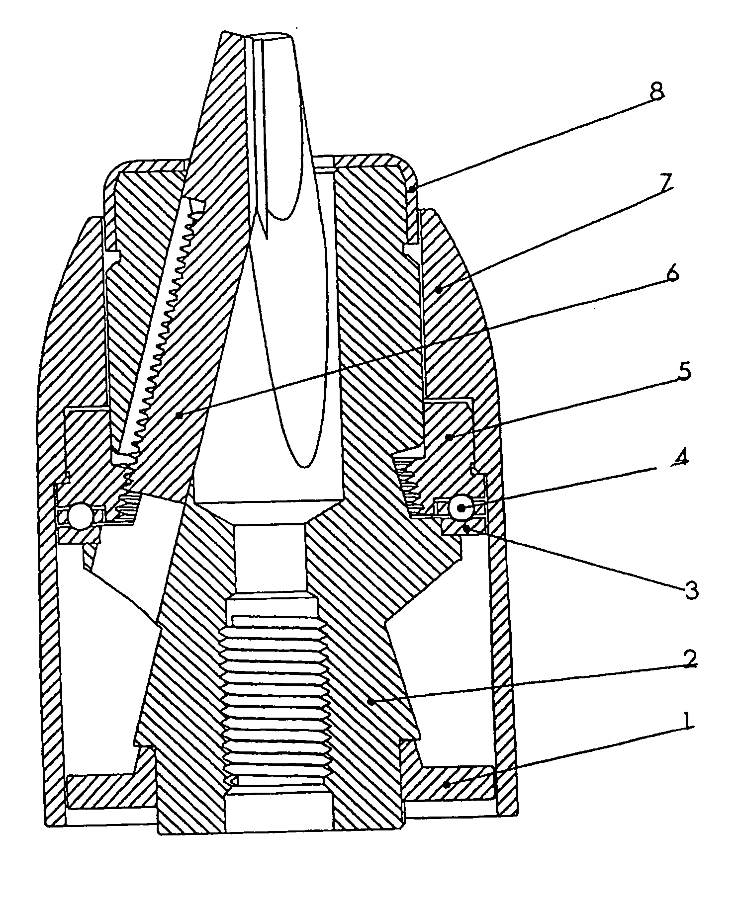
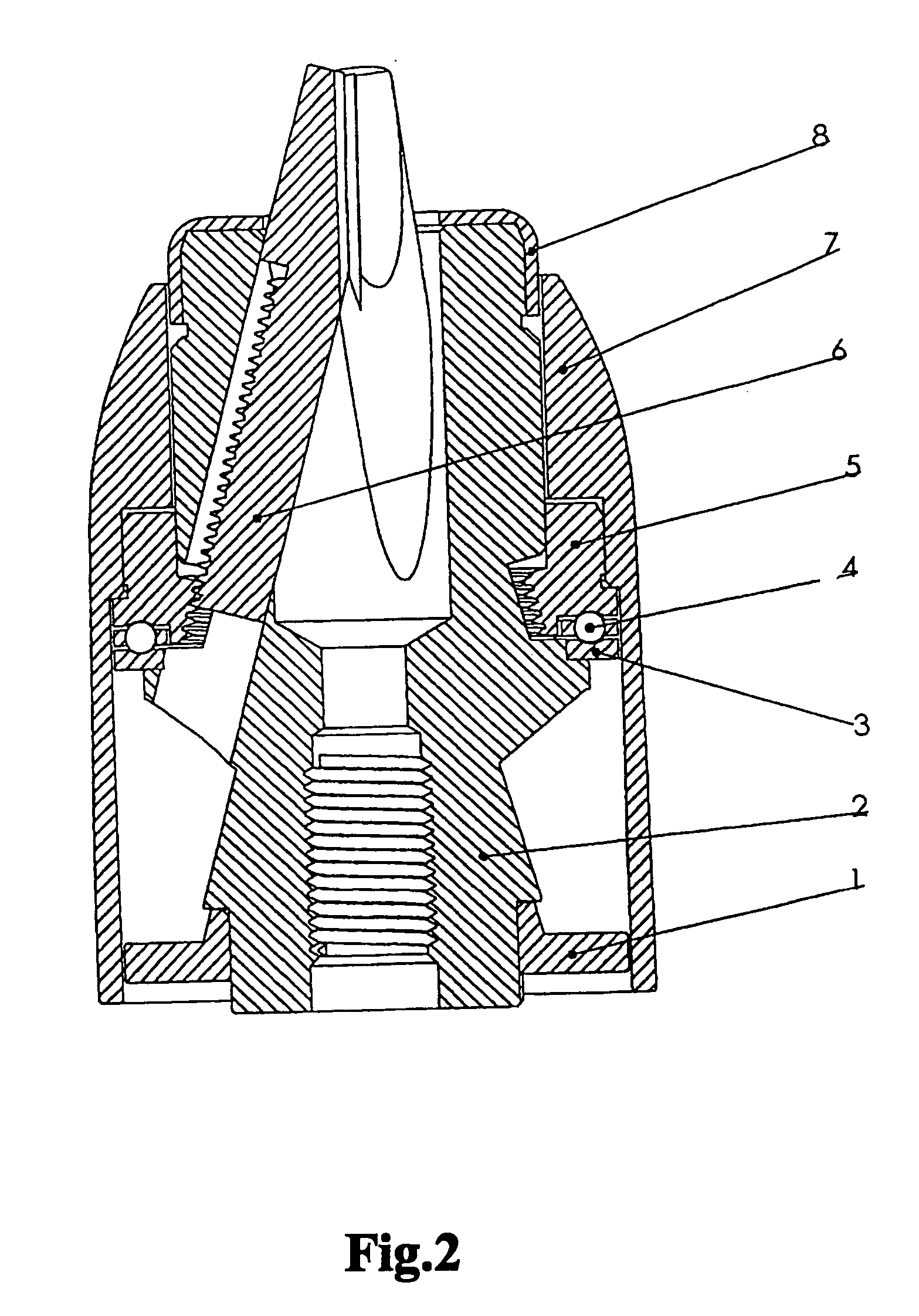
[0042]FIG. 2 is an axial, longitudinal sectional view of a self-tightening chuck according to an embodiment of the present invention, wherein the chuck comprises a rear sleeve 1, a body 2, a bearing ring 3, a bearing assembly 4, a nut 5, a jaw 6, a front sleeve 7 and a stopper 8. The relations of these elements are known in the art, and hence a detailed description thereof is omitted.

[0043] Referring to FIGS. 3, 4 and 5, the bearing ring 3 has a race surface that is provided with a circumferential arcuate race 9 with a fixed depth. When viewed from the cross section along line k-k, the circumferential arcuate race 9 has an arc radius R of 2.0 millimeters and a depth H of 0.15 millimeters. The circumferential arcuate race 9 has an arcuate bo...


PUM


Abstract

The present invention relates to a self-tightening keyless chuck to enable electric percussive drills to grip a tool shank. The chuck includes a rear sleeve, a body, a bearing ring, a bearing assembly, a nut, a jaw, a front sleeve and a stopper and so on. The bearing assembly utilizing a ball bearing is positioned with a circumferential arcuate race with a fixed depth, and the bottom surfaces of said circumferential arcuate race are provided with a plurality of ball-shape grooves. During the chuck grips a tool shank, the balls of said ball-bearing enter into the ball-shape grooves and are locked there, so as to prevent the tool from loosening due to the percussion vibration. In addition, the front sleeve engages with said nut through radial smooth press-fit to securely transmit a torque.

Description

FIELD OF THE INVENTION [0001] The present application relates to a keyless chuck and, more particularly, to a self-tightening keyless chuck. Generally, an electric percussive drill is capable of reciprocating, percussive vibration as well as rotary motion. Therefore, the present invention particularly provides a self-tightening keyless chuck for maintaining a secure grip on such a tool in percussive motion. BACKGROUND ART [0002] A variety of keyless chucks have been developed so far. A conventional chuck generally comprises a rear sleeve, a body, a bearing ring, a bearing, a nut, a jaw, a front sleeve, a stopper and so on. The jaw extends / retracts under the rotation of the nut and the engagement of conical threads, and the nut is rotated by movement of the front sleeve. Such a chuck is keyless if the front sleeve is rotated by hand. The chuck may be attached to a driving shaft of a drill by means of threads or a conical bore. [0003] A conventional keyed or keyless chuck has the disa...

Claims


Application Information

Patent Timeline
Patent Type & Authority Applications(United States)
IPC IPC(8): B23B31/12B23B45/14
CPCB23B31/1238Y10T279/17632Y10S279/902B23B2231/38
Inventor TIAN, XIANMINGPEI, HUIJUNSU, LIHANGXU, QIAOYU
Owner SHANXI HUIFENG POWER TOOLS
Why Eureka
Eureka Blog
Learn More