
Shopping cart basket

a shopping cart and basket technology, applied in the field of shopping carts, can solve the problems of protruding edges and unsatisfactory complexity

Inactive Publication Date: 2006-01-03
TARGET BRANDS
View PDF21 Cites 44 Cited by
  • Summary
  • Abstract
  • Description
  • Claims
  • Application Information

AI Technical Summary

Benefits of technology

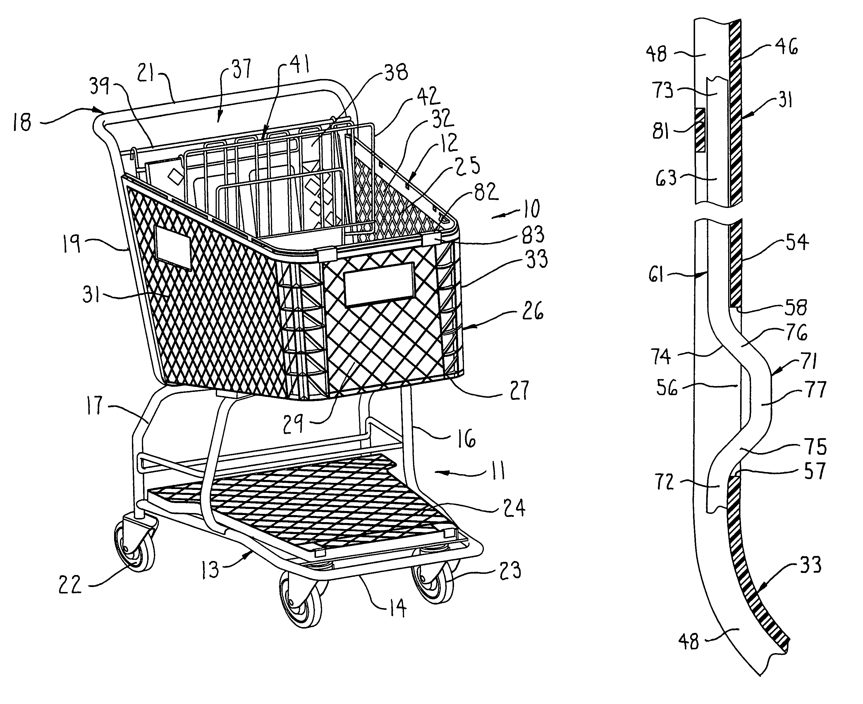
[0007]In the improved basket construction, as aforesaid, integral and monolithic protrusions on the support ring cooperate with the basket to simplify assembly of the support ring and basket while at the same time enabling the protrusions to function as gate stops positioned adjacent the upper edges of the side walls in the vicinity of the front wall. The gate stops create minimal visual disruption without creating any undesired sharp corners or edges.
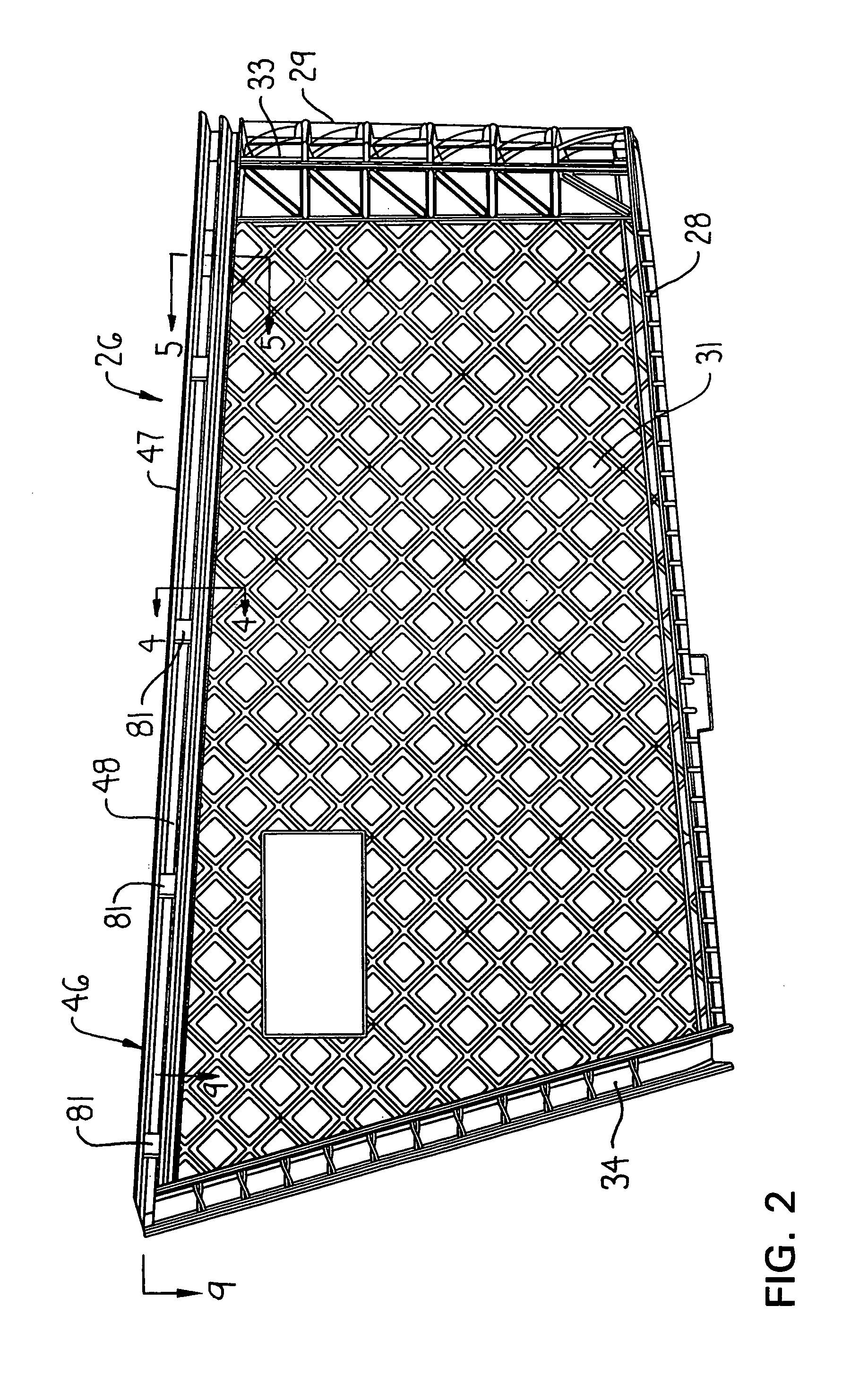
[0008]In the improved shopping cart basket construction of this invention, the basket is preferably of a molded one-piece plastic construction which defines the bottom wall, an upright front wall and a pair of opposed upright side walls, whereby the basket defines a large upwardly-opening storage compartment which is closed at its rear end by a separate rear gate assembly. The molded plastic basket has an outwardly-opening channel extending lengthwise along the front and side walls adjacent the upper edge thereof, and a generally U-shaped support rod is engaged within this channel. The support rod is formed from an elongate monolithic wire rod which is bent into a U-shaped form so as to have a front bight joined through rounded corners to a pair of cantilevered side legs which diverge relative to one another as they project toward their rear free ends. The side legs, at a location positioned adjacent but spaced rearwardly a small distance from the front bight, have U-shaped protrusions formed therein, as by a bending operation, with these protrusions protruding horizontally inwardly in generally opposed relationship to one another. The U-shaped support rod is mounted in the channel of the basket by slidably inserting the side legs into the channel parts along the upper edges of the side walls, which channel parts at spaced locations have loops extending thereover to effect closure of the channel at selected locations, whereby the legs slide through the loops for confinement in the channel. The side walls of the basket, adjacent but rearwardly of the front wall, also have small openings therethrough in communication with the channel. The insertion of the support rod into the channel causes the U-shaped protrusions to align with and pass through the openings in the side walls so that the protrusions protrude inwardly through the side walls beyond the inner surface thereof so as to permit their functioning as gate stops when baskets of like carts are nested. The protrusions also effectively lock the support rod relative to the basket in the longitudinal (i.e., front-to-back) direction thereof. The rear edges of the basket side walls abut against or are engaged with upright frame elements which define the rear handle of the basket, and these rear frame elements have openings in front sides thereof which align with the channel so that rear free ends of the side legs of the support rod can protrude into the openings formed in the upright frame elements, the latter preferably being hollow tubes, thereby restraining sideward or vertical movement of the rear ends of the support rod legs, and also permitting load as imposed from the basket on the support rod to be transferred directly onto the rear frame elements.

Problems solved by technology

A cart employing a basket of this type, namely having a continuous closed loop or ring extending around the basket and across the rear of the basket, is believed to result in undesired complexity with respect to assembly inasmuch as the upper walls of the basket have to be deformed and then moved into engagement with the ring after the ring has been positioned so as to extend around the handle frame uprights.
These constructions, as exemplified by U.S. Pat. No. 5,865,448, may perform as a gate stop in a satisfactory manner but require either increased complexities with respect to molding of the basket due to regions of increased material thickness, or increased complexities associated with forming of the support loop by requiring gate stops protruding above the top edges of the basket side walls, which stops also detract from appearance and result in protruding edges which can be harmful.

Method used


Image

  • Shopping cart basket
  • Shopping cart basket
  • Shopping cart basket

Examples


Embodiment Construction

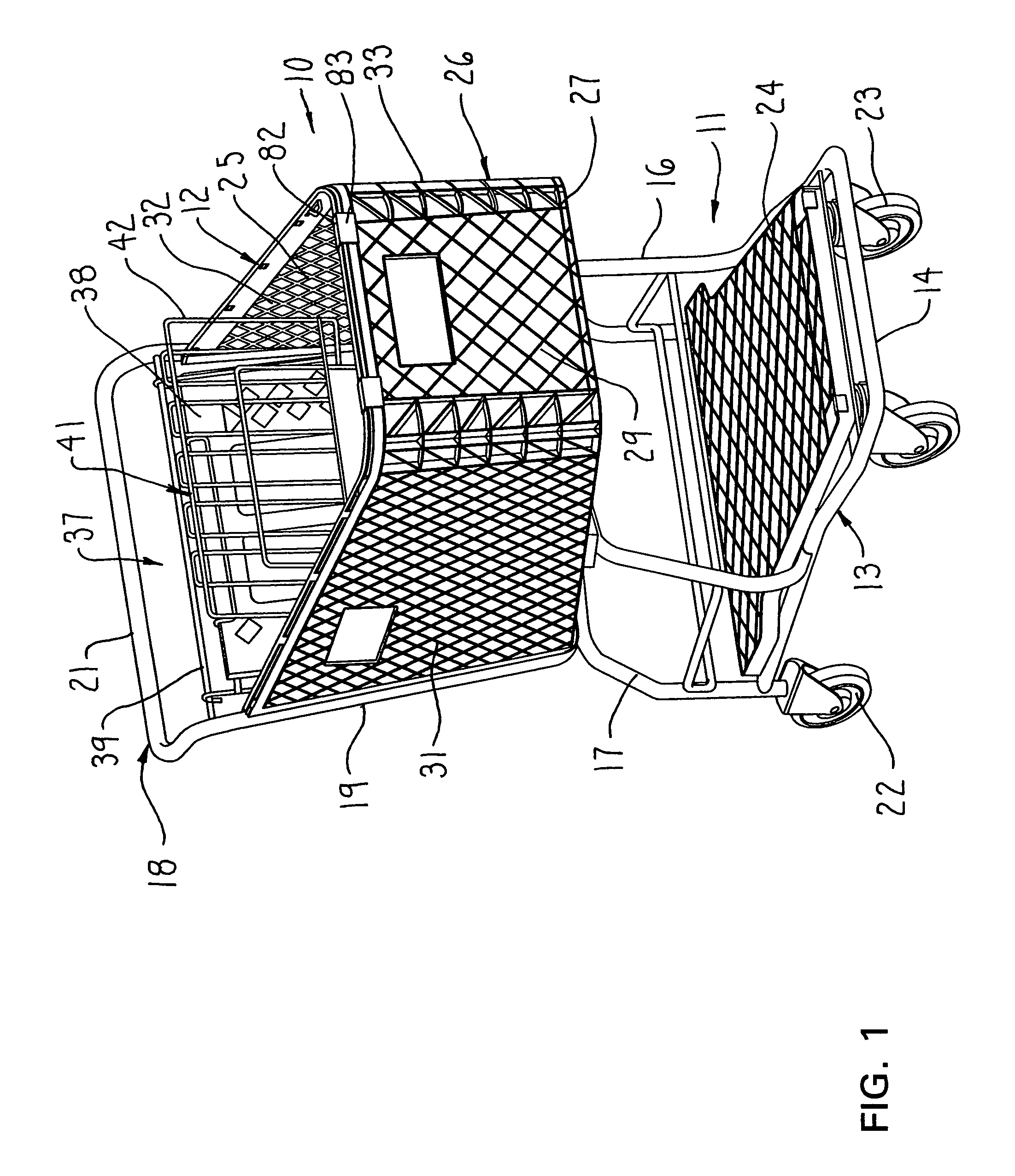
[0019]FIG. 1 illustrates a wheeled shopping cart which includes a wheeled frame or base assembly 11 on which a basket arrangement 12 is supported.

[0020]The frame assembly 11 includes a generally rigid base frame 13 having a generally horizontally oriented U-shaped base member 14. Generally inverted U-shaped intermediate and rear basket supports 16 and 17 are fixed to and project upwardly from the base member 14 for engaging the underside of the basket arrangement 12. A generally inverted U-shaped or ring-shaped rear frame 18 includes a pair of generally parallel side legs or frame elements 19 which extend along and rigidly secure to the rear edges of the basket. The ring-shaped rear frame 18, adjacent the lower ends of the side legs 19, has a cross rod which is rigidly joined to the top cross rod of the rear upright 17. The upper ends of side legs 19 are joined by a cross rod or handle 21 which extends transversely across the cart adjacent the rear upper edge of the basket.

[0021]The...


PUM

PropertyMeasurementUnit
Distanceaaaaaaaaaa

Abstract

A molded plastic basket associated with a wheeled shopping cart, which plastic basket has a generally U-shaped support rod engaged within an elongate channel extending along upper edges of the side and front walls of the basket. The support rod has constructional features to provide for desirable supportive engagement and reinforcement of the upper edge of the basket while at the same time permitting coupling of the support rod and basket to the rear frame uprights to facilitate assembly while providing desirable load transmission from the basket to the upright frame elements.

Description

FIELD OF THE INVENTION[0001]This invention relates to a wheeled shopping cart and, more specifically, to improvements associated with a plastic basket as provided on the cart.BACKGROUND OF THE INVENTION[0002]Wheeled shopping carts as conventionally utilized in department stores, supermarkets and related environments typically employ a large upwardly-opening basket for accommodating merchandise therein. The basket normally has a rear wall, known as a rear gate, associated with the handle end thereof and pivotally supported adjacent its upper edge to permit such carts to be nested one within another during storage of the carts. This rear gate also conventionally mounts a foldable seat assembly thereon for accommodating a small child. Many of these carts construct the basket of plastics material, with such basket frequently being of a one-piece molded plastic construction defining the bottom, front and opposed side walls.[0003]In one known cart employing a molded plastic basket, a clos...

Claims


Application Information

Patent Timeline
IPC IPC(8): B62B3/02
CPCB62B3/14Y10S280/04B62B2501/065B62B3/1496
Inventor TUCKER, JAMES B.RUGER, VERLYN C.HUBBARD, LARRY S.
Owner TARGET BRANDS
Learn More