
Distal end for cryoablation catheters

a catheter and distal end technology, applied in the field of interventional medical devices, to achieve the effect of increasing resistance and reducing pressur

Inactive Publication Date: 2006-01-03
CRYOCOR
View PDF67 Cites 57 Cited by
  • Summary
  • Abstract
  • Description
  • Claims
  • Application Information

AI Technical Summary

Problems solved by technology

In the context of a cryo-catheter, “A” will be predetermined and will be necessarily limited by space considerations.

Method used


Image

  • Distal end for cryoablation catheters
  • Distal end for cryoablation catheters
  • Distal end for cryoablation catheters

Examples


Embodiment Construction

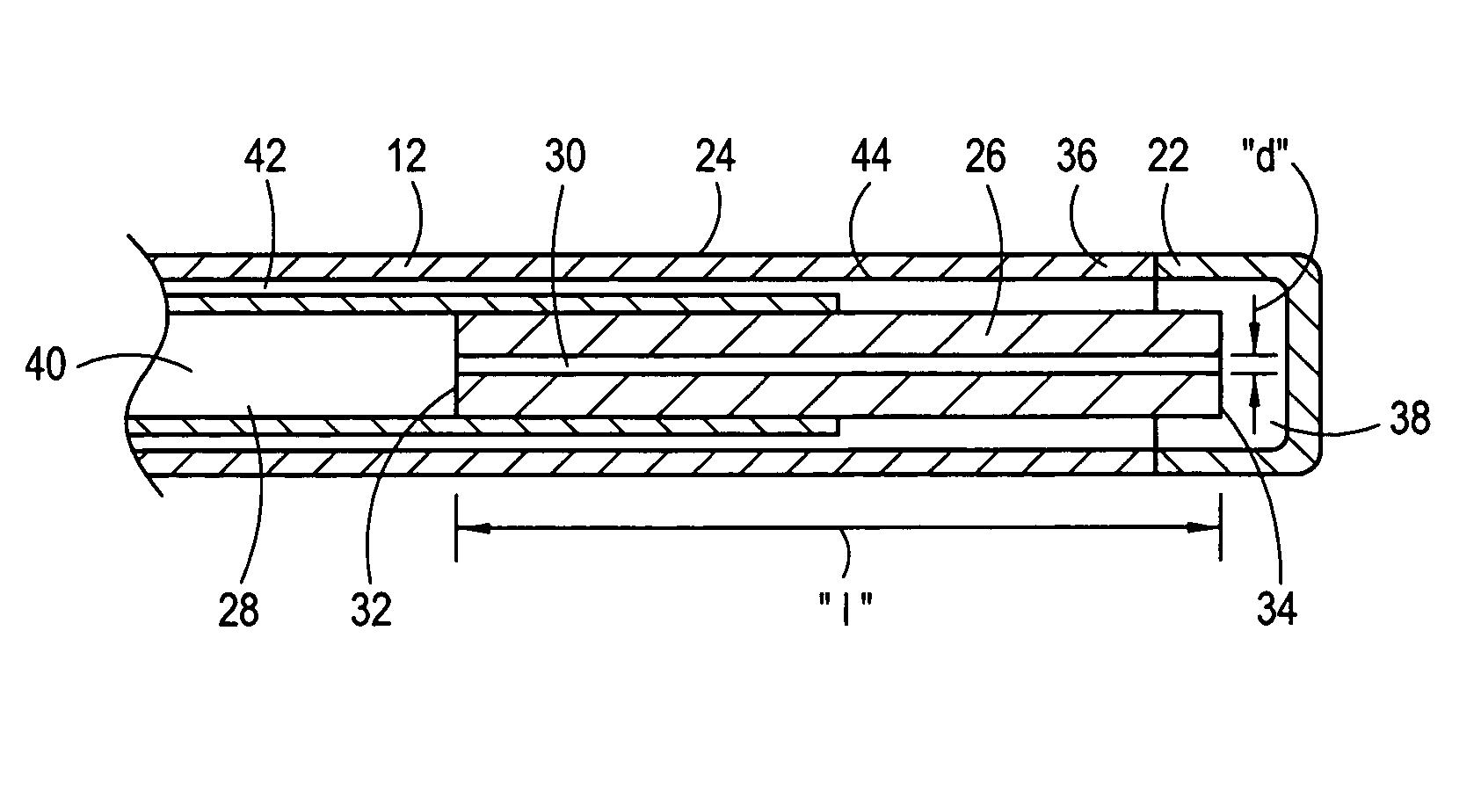
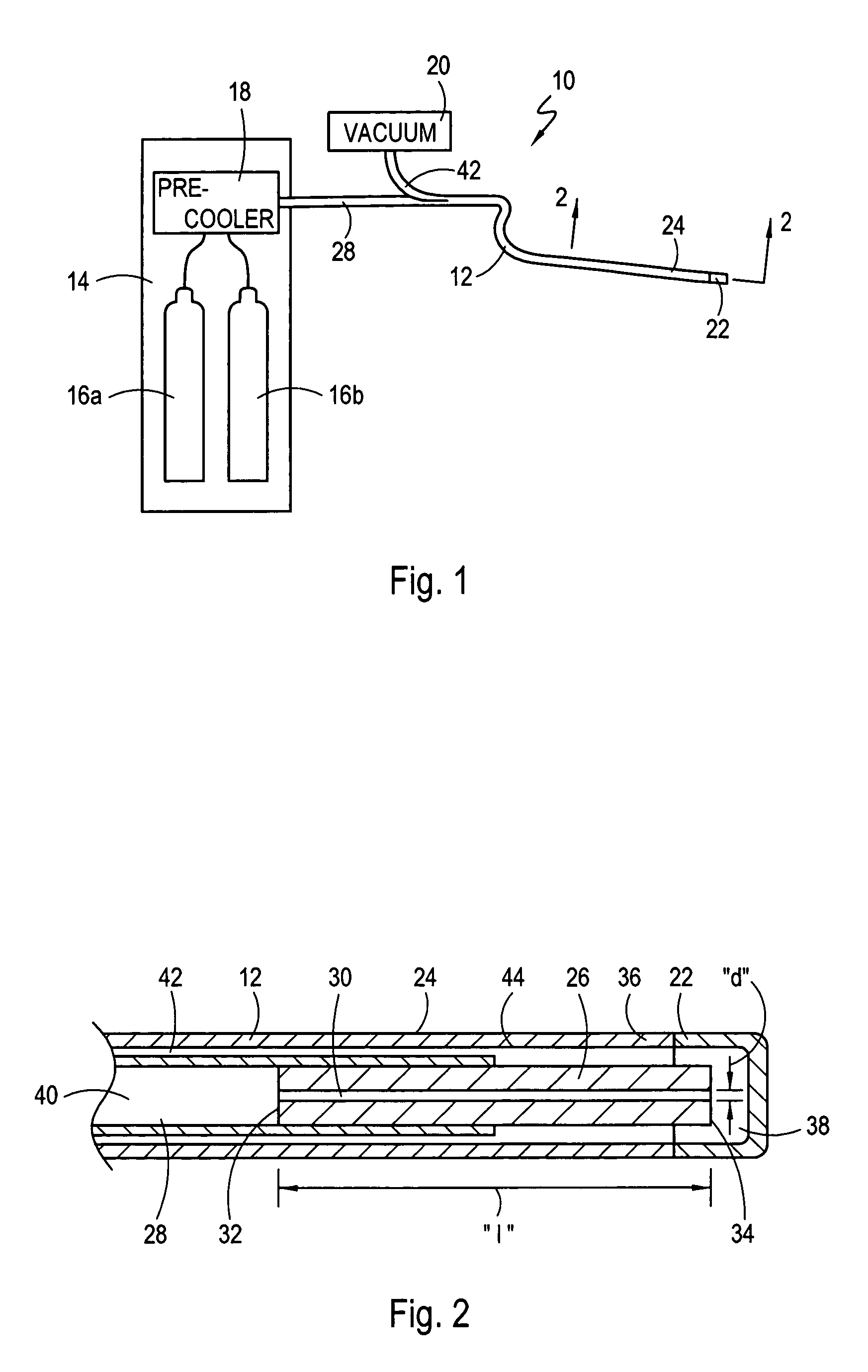
[0021]Referring initially to FIG. 1, a system in accordance with the present invention is shown and is generally designated 10. In detail, the system 10 is shown to include a cryo-catheter 12 that is connected to a console 14 and in fluid communication with a pair of fluid refrigerant sources 16a and 16b that are mounted inside the console 14. The sources 16a and 16b shown in FIG. 1 are, however, only exemplary. As envisioned for the present invention, the refrigerant sources 16a and 16b may be of any type pressure vessel known in the pertinent art that is suitable for holding a fluid under relatively high pressures (e.g. 700 psia). For the purposes of the present invention, the fluid refrigerant that is held in sources 16a and 16b will preferably be nitrous oxide (N2O). Still referring to FIG. 1 it is seen that the fluid refrigerant sources 16a and 16b are connected in fluid communication with a pre-cooler 18. The pre-cooler 18, in turn, is connected in fluid communication with the...


PUM


Abstract

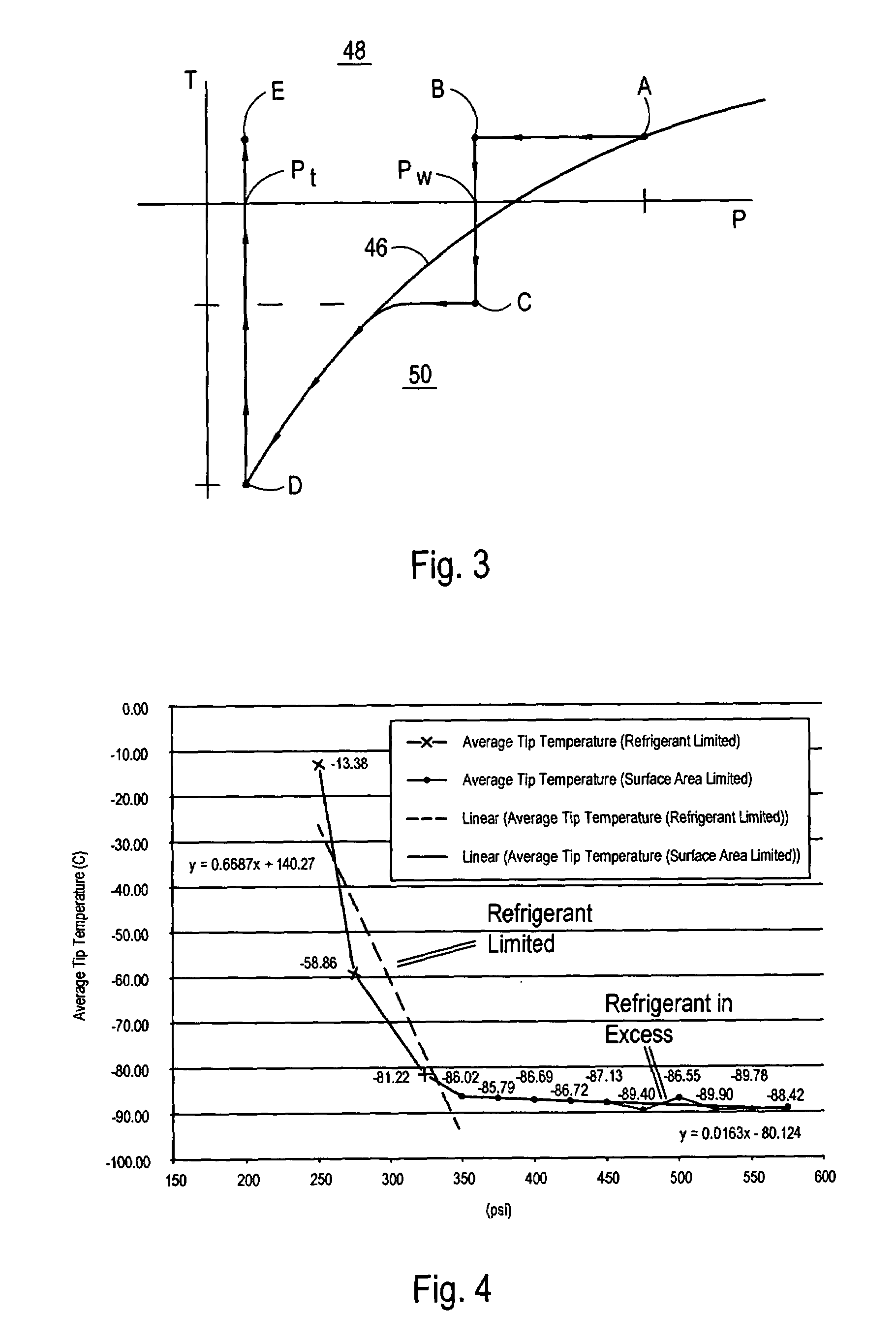
A system and method for transferring heat requires a supply tube connected in fluid communication with a capillary tube. A tip member is positioned to surround the distal end of the capillary tube to create a cryo-chamber. In operation, a liquid refrigerant is introduced into the supply tube at a working pressure (e.g. 450 psia). The pressure is then significantly reduced on the liquid refrigerant as it transits through the capillary tube. The refrigerant then exits the distal end of the capillary tube, still in its liquid state. Inside the cryo-chamber, at a pressure of less than about one atmosphere, the refrigerant transitions into its gaseous state. The resultant refrigeration causes heat to transfer into the cryo-chamber.

Description

FIELD OF THE INVENTION[0001]The present invention pertains generally to interventional medical devices that can be advanced into the vasculature of a patient. More particularly, the present invention pertains to cryo-catheters that are useful for cryoablating tissue in the vasculature. The present invention is particularly, but not exclusively, useful for the construction and deployment of a cryo-catheter wherein a refrigerant fluid transitions from a liquid to a gaseous state, at an operational site in the vasculature, to establish cryoablation temperatures that are below approximately minus eighty four degrees Centigrade.BACKGROUND OF THE INVENTION[0002]Medical devices that can be advanced into the vasculature of a patient, and properly positioned at a site for an in-situ procedure, have several structural requirements in common with each other. Most importantly, they must be properly dimensioned to allow them to be advanced into the vasculature. This requires they be long and sle...

Claims


Application Information

Patent Timeline
Patent Type & Authority Patents(United States)
IPC IPC(8): F25D15/00A61B18/02A61B17/00
CPCA61B18/02A61B2018/0262A61B2018/0212
Inventor LENTZ, DAVID J.RIORDAN, MATT M.RYBA, ERIC
Owner CRYOCOR
Learn More