
Coils for high frequency MRI

a high-frequency mri and coil technology, applied in the field of spatially sensitive nmr instrumentation, can solve the problems of undesirable dimensional constraint of the surface coil, achieve the effect of reducing the effective inductance of the transmission line, facilitating relatively higher resonant frequency resonant response, and narrowing the band respons

Inactive Publication Date: 2005-12-27
AGILENT TECH INC
View PDF29 Cites 53 Cited by
  • Summary
  • Abstract
  • Description
  • Claims
  • Application Information

AI Technical Summary

Benefits of technology

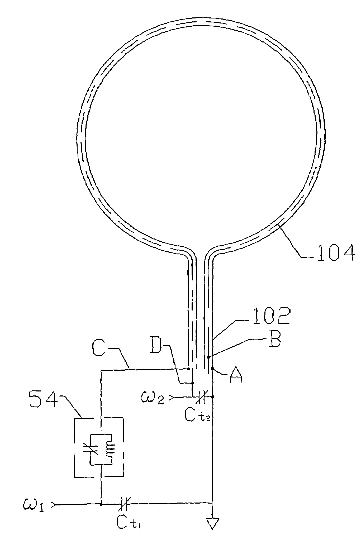
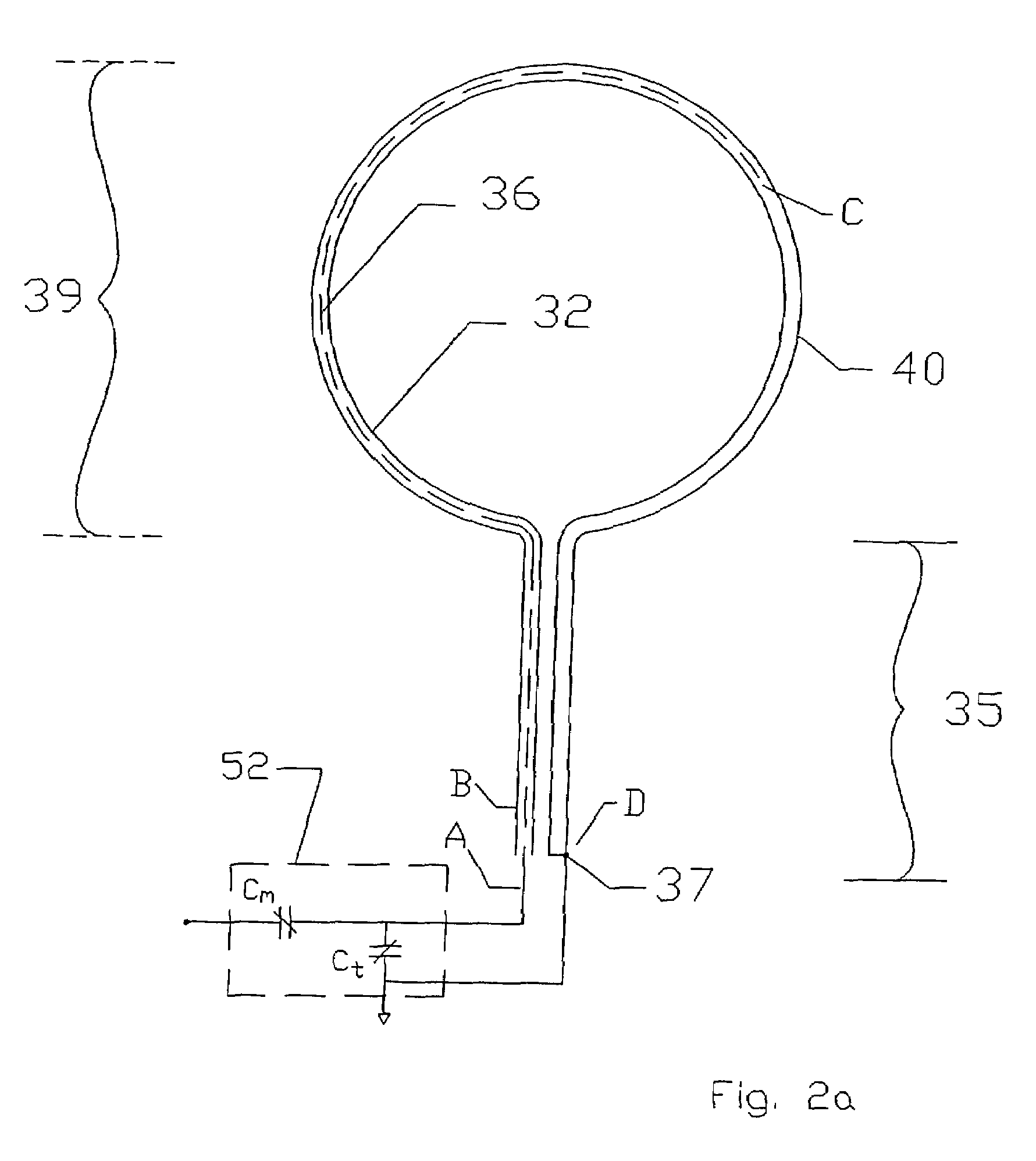
[0008]The introduction of one (or more) gaps in a conductive member of a transmission line is the analytic equivalent of two (or more) serially communicating transmission lines. One practical functional effect of the gap is to reduce the effective inductance of the transmission line relative to the distributed capacitance, thus facilitating relatively higher resonant frequency resonant response for a circuit comprising the transmission line in common mode. Embodiments of the transmission line surface coil of this invention, incorporating increasing multiple gaps (in opposite conductors, arranged in staggered fashion) are found to exhibit increasingly narrow band response.

Problems solved by technology

Ladder networks have been employed in prior art but it will be apparent that the construction of any ladder network / surface coil requires careful selection of discrete circuit components to preserve the design integrity of the circuit as well as laborious manufacture of the coil from a variety of components.
The dimensional constraint on surface coils is undesirable.

Method used


Image

  • Coils for high frequency MRI
  • Coils for high frequency MRI
  • Coils for high frequency MRI

Examples


Embodiment Construction

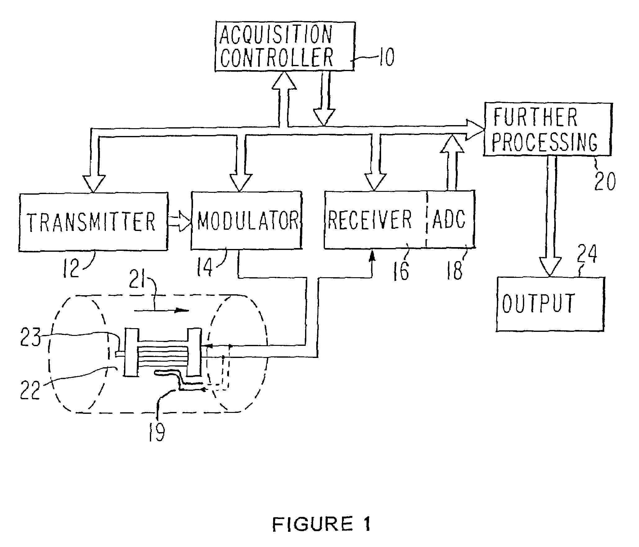
[0035]FIG. 1 represents the context of the invention represented by a schematicised general NMR instrument. An acquisition / control processor 10 communicates with an RF source 12, modulator 14 and RF receiver 16, including analog-to-digital convertor 18 and a further digital processor 20. The modulated RF power ordinarily comprises a sequence of RF pulses of specified frequency content, duration and phase and irradiates an object / sample 23 in a magnetic field 21 through (volume) excitation coil 22. Other magnetic field components or gradients may be superimposed upon magnetic field 21 in predetermined synchronization with the RF modulation. Response of the sample / object is intercepted by the same coil 22 or alternatively, coil 19 communicating with receiver 16. The coil(s) 22 and / or 19 may have a volume or surface geometry as may be appropriate to the particular investigation. The response typically takes the form of a transient time domain waveform or free induction decay. This tran...


PUM


Abstract

NMR coils are formed from transmission line comprising a tuned LC circuit determined substantially from the distributed capacitance and inductance of the transmission line operated in common mode. Introduction of gaps staggered between opposite conductors of 2-conductor transmission line contribute a desired distributed capacitance with reduced effective inductance to sustain resonant behavior at higher frequency than achievable with conventionally tuned coils and with relaxation of dimensional constraints as the resonant half wavelength approaches coil dimensions.

Description

FIELD OF THE INVENTION[0001]The invention is in the field of spatially sensitive NMR instrumentation and relates to resonant coils of novel construction and particularly to surface coils for localized magnetic resonance studies.BACKGROUND OF THE INVENTION[0002]NMR investigation of selected interior regions of an object have long employed a surface coil disposed on the exterior surface of the object proximate a region of interest to localize an RF resonance signal incident to magnetic resonance excitation. A surface coil has the attributes of an antenna and is desirably of no significantly greater extent than the region of interest. The surface coil is often analogized to a loop antenna in combination with a tunable resonant circuit. The ideal surface coil provides strong coupling to a delimited region of the object with enhanced sensitivity and minimal radiation losses.[0003]In typical imaging instrumentation and usage, excitation of nuclear resonance is effected with a volume coil ...

Claims


Application Information

Patent Timeline
IPC IPC(8): G01R33/34
CPCG01R33/34053G01R33/34069G01R33/341
Inventor WONG, WAI HALEUNG, JIMMYFUNK, ALEXANDERMEHR, KNUT
Owner AGILENT TECH INC
Learn More