Wheelchair braking device

a technology for braking devices and wheelchairs, which is applied in the direction of brake systems, wheelchairs/patient conveyances, friction linings, etc., can solve the problems of significant risk of user falling, braking mechanisms are relatively complicated, and wheelchairs require considerable modification, etc., to achieve the effect of being easily retrofitted

Inactive Publication Date: 2005-12-27
PERON JIM +2
View PDF7 Cites 2 Cited by
  • Summary
  • Abstract
  • Description
  • Claims
  • Application Information

AI Technical Summary

Benefits of technology

[0010]To fully immobilize a wheelchair, two braking devices in accordance with this invention are preferably installed, with each braking device being dedicated to brake one of the large wheels of the wheelchair. From the above description, it can be appreciated that the automatic braking capability

Problems solved by technology

While such brake mechanisms are reliable, the operator or user of a wheelchair may forget to engage the lever prior to entering or leaving the seat.
If the wheelchair is not properly immobilized by the brake, there is a significant risk of the user falling while trying to stabilize him or herself when entering or leaving the wheelchair.
However, these braking mechanisms are relatively complicated and / or require considerable modification to the wheelchair.
However, solenoids and batteries sufficiently powerful to overcome the spring force contribute significantly to the cost of the wheelchair.

Method used


Image

  • Wheelchair braking device
  • Wheelchair braking device

Examples


Embodiment Construction

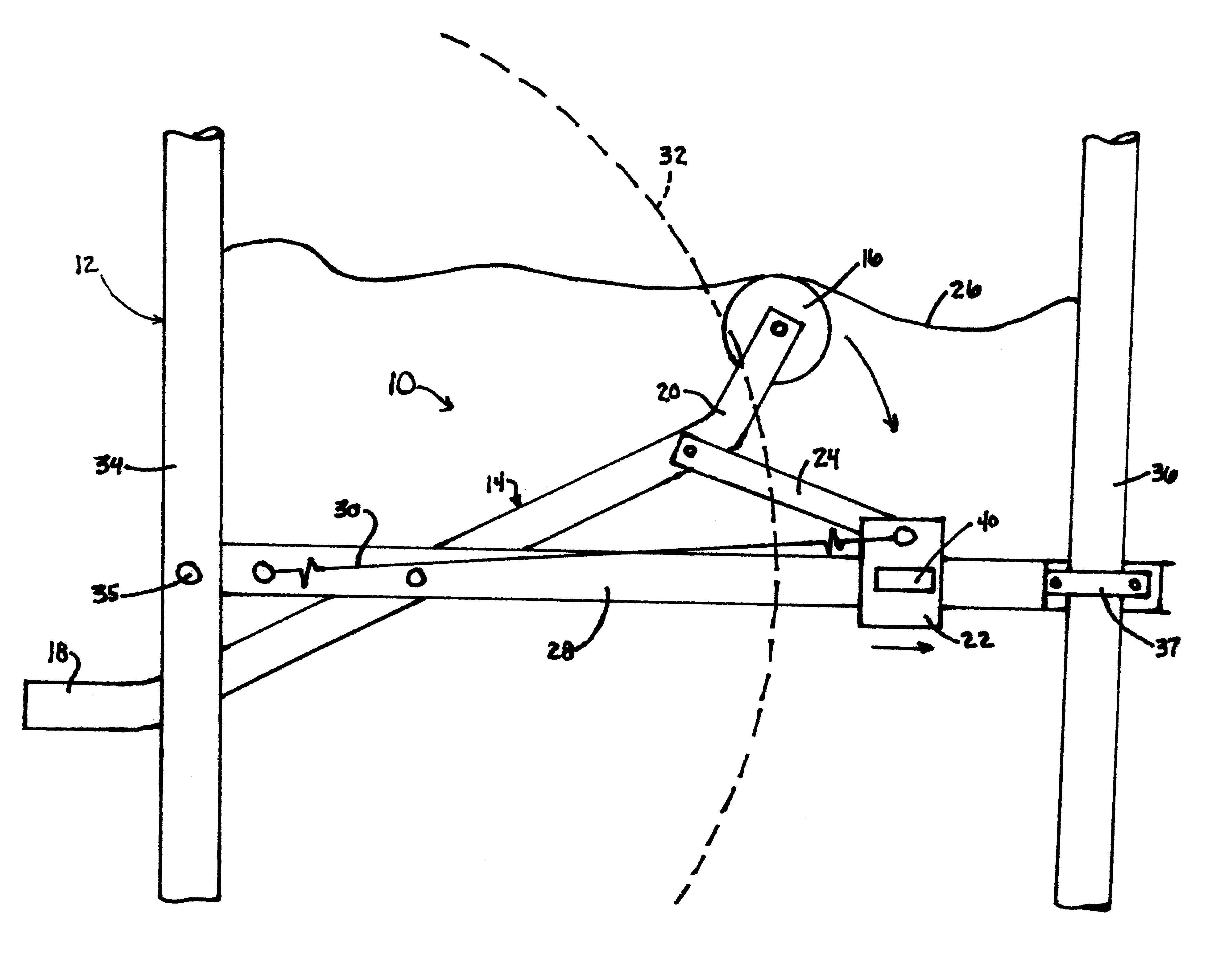
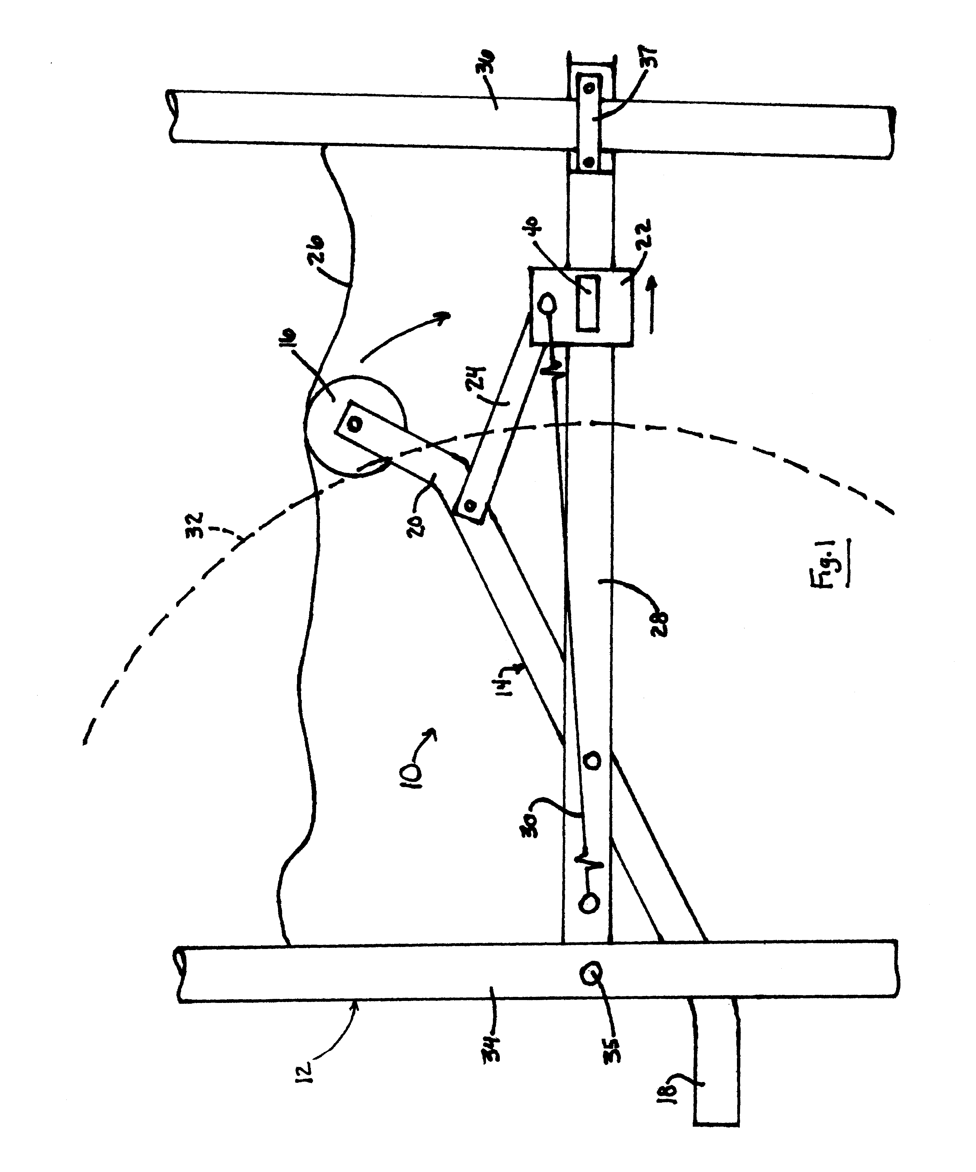
[0013]A wheelchair braking device 10 in accordance with a preferred embodiment of this invention is illustrated in FIG. 1. As shown, the braking device 10 is mounted to a conventional wheelchair 12, whose structure and components need not be modified or removed to accommodate the braking device 10. As such, the braking device 10 is configured to be mountable to essentially any conventional wheelchair, including those designed to be collapsible.

[0014]Though a single braking device 10 is shown, two units of the braking device 10 shown in FIG. 1 are intended to be installed on the wheelchair 12, one on each side of the wheelchair 12 to operate on one of two larger wheels 32 (one of which is shown in phantom). Each device 10 includes a support bar 28 oriented in a fore-aft (longitudinal) direction of the wheelchair 12. The bar 28 is secured to aft and fore vertical frame members 34 and 36 of the wheelchair 12, such as with a fastener 35 as shown for the aft frame member 34 and a clamp 3...


PUM


Abstract

A wheelchair braking device providing a braking action that automatically disengages when an occupant is seated in the wheelchair. The braking device includes a support structure to which a sensing lever is pivotably mounted and to which a braking arm is slidably mounted. A biasing element is coupled to the braking lever to bias the braking arm in a first direction relative to the support structure and into engagement with a wheel of the wheelchair, thereby inhibiting rotation of the wheel. The sensing lever and braking arm are interconnected such that the biasing element operates through the braking arm to bias the sensing lever in an upward direction against the wheelchair seat. The interconnection between the sensing lever and braking arm causes the braking arm to disengage from the wheel when the sensing lever rotates in a downward direction.

Description

CROSS REFERENCE TO RELATED APPLICATIONS[0001]This application claims the benefit of U.S. Provisional Application No. 60 / 319,590, filed Oct. 2, 2002. In addition, this application is related to commonly-assigned U.S. Pat. No. 5,894,912, the contents of which are incorporated herein by reference.BACKGROUND OF INVENTION[0002]1. Field of the Invention[0003]The present invention generally relates to braking devices for wheelchairs and similar vehicles. More particularly, this invention relates to a wheelchair braking device having an uncomplicated construction that can be installed on conventional wheelchairs, and which provides a braking action that automatically disengages when an occupant is seated in the wheelchair.[0004]2. Description of the Related Art[0005]Wheelchairs are generally equipped with a brake mechanism to enable the user to more safely enter and leave the seat of the wheelchair. Conventional braking mechanisms typically consist of a pair of levers, each engaging the ext...

Claims


Application Information

Patent Timeline
IPC IPC(8): B62B5/04
CPCA61G5/101A61G5/1018A61G5/1035B62B5/0404B62B5/0409
Inventor PERON, JIMLEAHY, JONATHANDOBBENS, STEVEN
Owner PERON JIM
Why Eureka
Try Eureka