
Contact surface for a crimping roller in a roll forming tool

a technology of contact surface and crimping roller, which is applied in the field of rolling forming tools, can solve the problems of uneven thickness of weather strip, inconvenient installation of weather strip, and inability to meet the needs of fewer metal layers,

Inactive Publication Date: 2005-12-27
SCHLEGEL
View PDF27 Cites 5 Cited by
  • Summary
  • Abstract
  • Description
  • Claims
  • Application Information

AI Technical Summary

Problems solved by technology

The fitting of flange mounted automotive weatherstrips encounters a number of traditional problems resulting from manufacturing tolerances in both the weatherstrip and the vehicle.
If the weatherstrip is formed to accommodate the predetermined thickness, the weatherstrip may be too wide for a flange of fewer metal layers, yet too narrow for a flange of more metal layers.
As a result, the weatherstrip may not grip satisfactorily where the flange is of fewer layers and conversely, if the flange is of excess layers, the weatherstrip may be extremely difficult to install.
However, it has been found that while the splayed flange-gripping construction offers significant advantages and in the accommodation of varying flange thickness, there is a significant tendency of the rollers to embed into the surface of the seal (upon excessive flange thickness) or spin relative to the seal without corresponding movement along the length of the seal, thereby marring the surface of the strip.
Such marring, if on the edge trim portion can reduce the esthetic appeal, and if upon the sealing portion, can damage the seal to reduce its effective sealing capacity.

Method used


Image

  • Contact surface for a crimping roller in a roll forming tool
  • Contact surface for a crimping roller in a roll forming tool
  • Contact surface for a crimping roller in a roll forming tool

Examples


Embodiment Construction

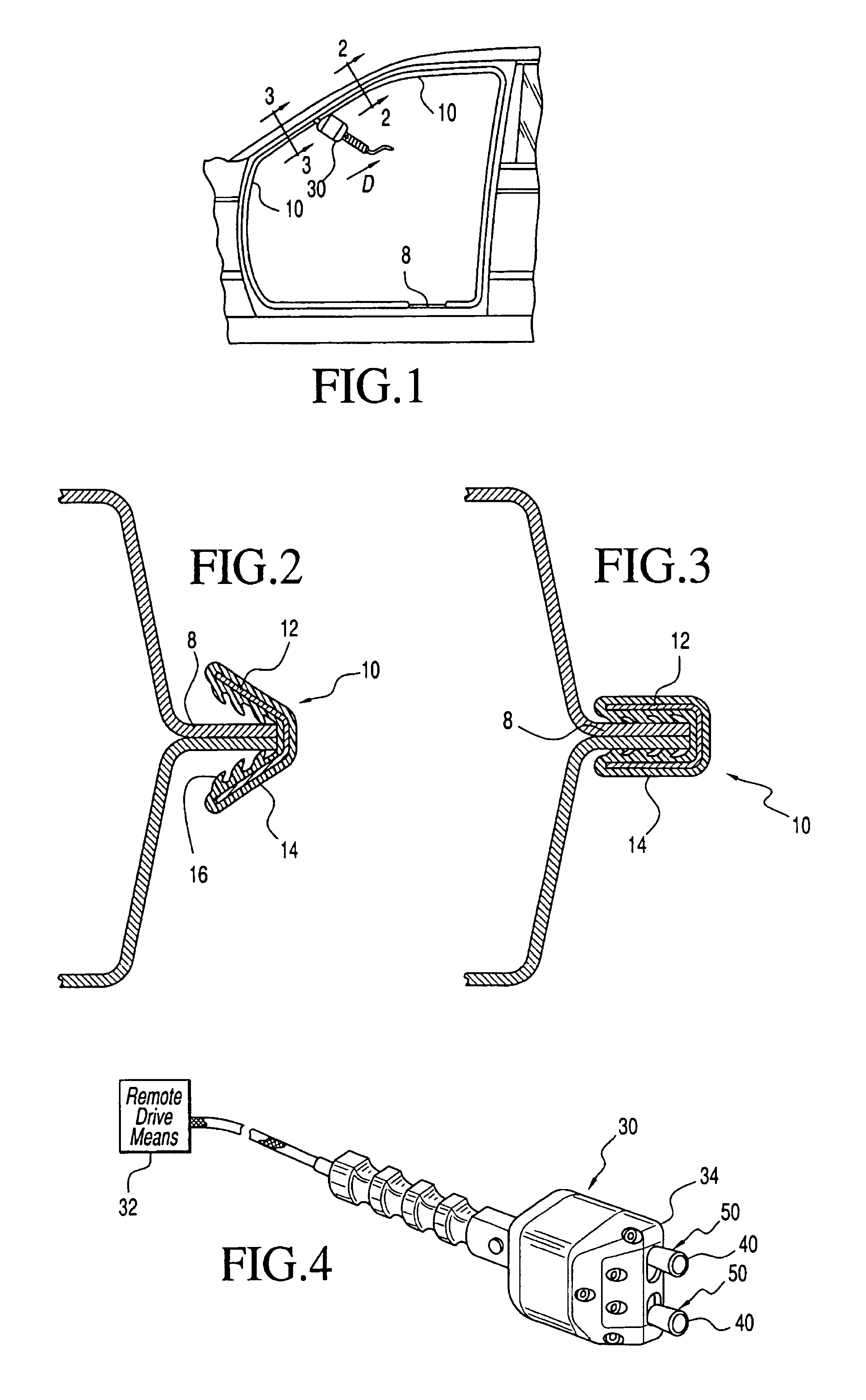
[0041]Referring to FIGS. 1 and 2, a roll forming tool 30 is shown operably engaging a splayed flange cap 10 on a vehicle flange 8.

[0042]Typically, an edge trim or seal includes the generally U-shaped flange cap 10. The flange cap 10 typically includes a reinforcing member 12 at least partially surrounded by a polymeric body 14 to define the U shape profile.

[0043]The polymeric material 14 of the flange cap 10 can be any of a variety of materials such as thermoplastics, elastomers or combinations thereof.

[0044]A typical reinforcing member 12 has sufficient rigidity to be crimped onto the flange and operably retain the flange cap 10. The reinforcing member has a U shaped profile corresponding to the flange cap 10. The reinforcing member 12 can be a plastic, metal, composite or alloy. Satisfactory reinforcing members 12 include a metal core, a knitted wire, a lanced metal or a stamped metal.

[0045]The flange cap 10 is originally presented to a flange 8 in an open condition shown in FIGS....


PUM

PropertyMeasurementUnit
angleaaaaaaaaaa
diametersaaaaaaaaaa
diametersaaaaaaaaaa

Abstract

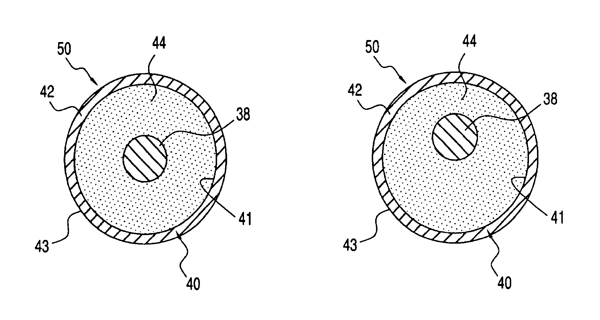
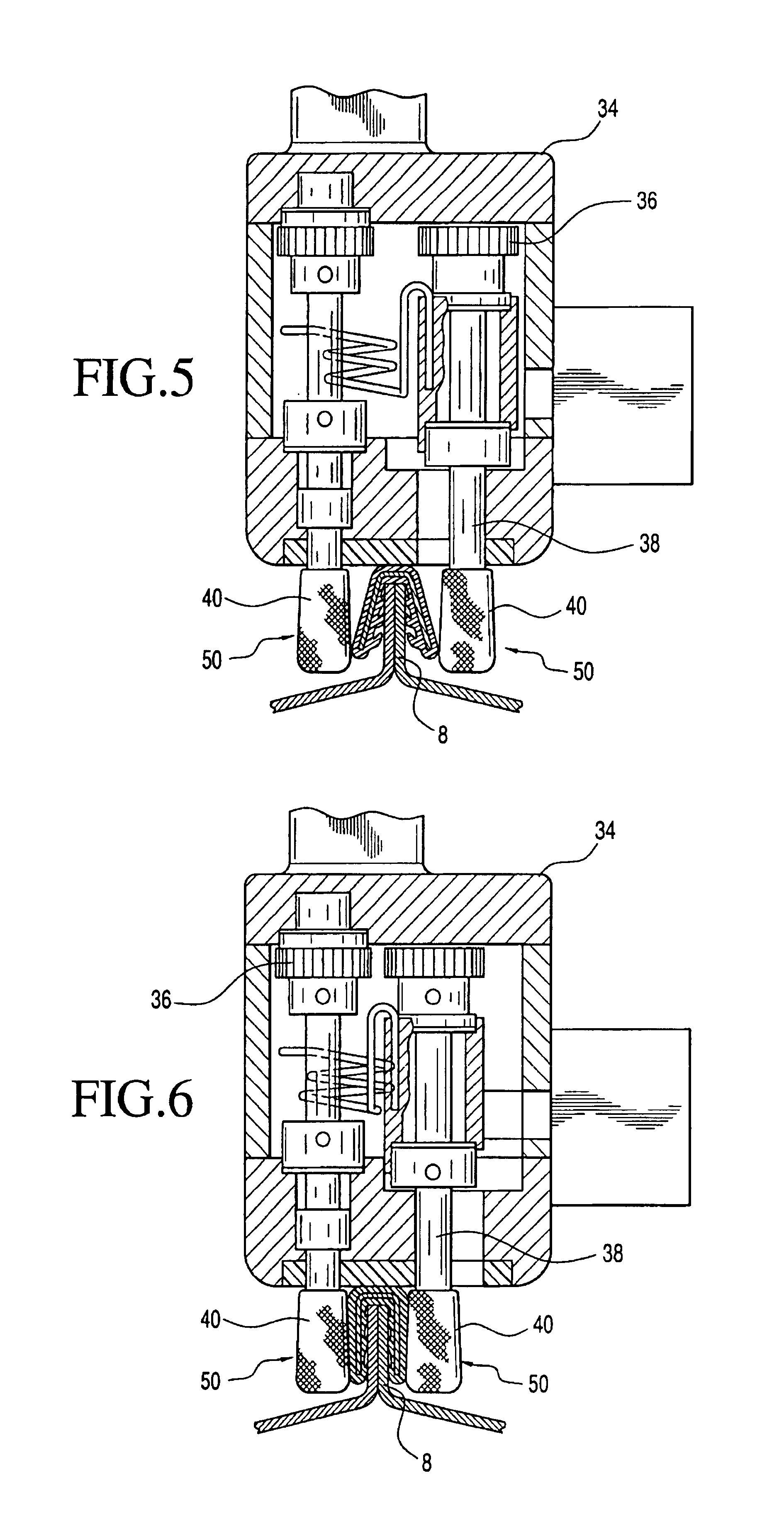
A roll-forming tool for deforming a flange cap from a splayed configuration to engage a vehicle flange, the tool includes a polymeric contact surface disposed about a rigid drum. The polymeric contact surface can be in the form of a sleeve and integrally formed to the metal drum, or alternatively, the sleeve can be removeably attached to the drum for allowing replacement. The drums can be metal and configured for eccentric rotation relative to a corresponding drive shaft, thereby accommodating further variations in flange thickness.

Description

CROSS-REFERENCE TO RELATED APPLICATIONS[0001]Not applicable.STATEMENT REGARDING FEDERALLY SPONSORED RESEARCH OR DEVELOPMENT[0002]Not applicable.REFERENCE TO A “SEQUENCE LISTING”[0003]Not applicable.BACKGROUND OF THE INVENTION[0004]1. Field of the Invention[0005]The present invention relates to roll forming tools for crimping an edge trim or seal onto a flange of a motor vehicle, and more particularly, to a contact surface for a crimping roller in the roll forming tool, wherein the contact surface provides the necessary friction between the roll forming tool and the edge trim or seal, while minimizing surface damage to the edge trim or seal during installation (crimping) operations.[0006]2. Description of the Related Art[0007]The fitting of flange mounted automotive weatherstrips encounters a number of traditional problems resulting from manufacturing tolerances in both the weatherstrip and the vehicle.[0008]Traditional flange mounted weatherstrips include a U-shaped profile having a...

Claims


Application Information

Patent Timeline
Patent Type & Authority Patents(United States)
IPC IPC(8): B23P19/04B60J10/00
CPCB23P19/047B60J10/0088Y10T29/53791B60J10/45
Inventor ROSENAU, KEITH W.ROYSE, MARION A.LAGERSTROM, MICHAEL J.KONITSNEY, WILLIAM J.
Owner SCHLEGEL
Learn More