
Structure of a rivet nut gun

a rivet nut and gun body technology, applied in the field of rivet nut guns, can solve the problems of complex parts and their assembly in the rivet nut gun, and achieve the effect of convenient assembling and maintenance of the gun

Inactive Publication Date: 2005-12-27
LIN YU CHING
View PDF4 Cites 30 Cited by
  • Summary
  • Abstract
  • Description
  • Claims
  • Application Information

AI Technical Summary

Benefits of technology

[0005]The prime object of the present invention is to provide a rivet nut gun, in which the body, the handle and the pressure cylinder are assembled together by means of a connecting rod and a nut; such a structure can facilitate the assembling and maintenance of the gun. An another object of the present invention is to provide a rivet nut gun, in which the pressure cylinder and the body are assembled together by means of screw rods to cause the piston cylinder in the pressure cylinder and the inner round surface of a lid in the handle to be in close and hermetic contact; by means of such structure, the assembled parts thereof would not be deformed during operation of the gun.

Problems solved by technology

A conventional rivet nut gun usually comprises a body, a handle mounted under the body, and a pressure cylinder under the handle; the pressure cylinder includes a piston and a piston rod mounted in the cylindrical hole of the handle; through a pipe, a pressure air can flow into the lower space of the pressure cylinder to push the piston to move; then, a liquid in a hydraulic chamber will be pushed to provide a pressure to actuate the rivet nut gun; however, the parts and their assembling in the rivet nut gun are complex; the pressure cylinder is usually made of a pressure-proof metal, and is to be fastened under the handle; otherwise, a deformation would take place between the pressure cylinder and the handle as a result of riveting operation.

Method used


Image

  • Structure of a rivet nut gun
  • Structure of a rivet nut gun
  • Structure of a rivet nut gun

Examples


Embodiment Construction

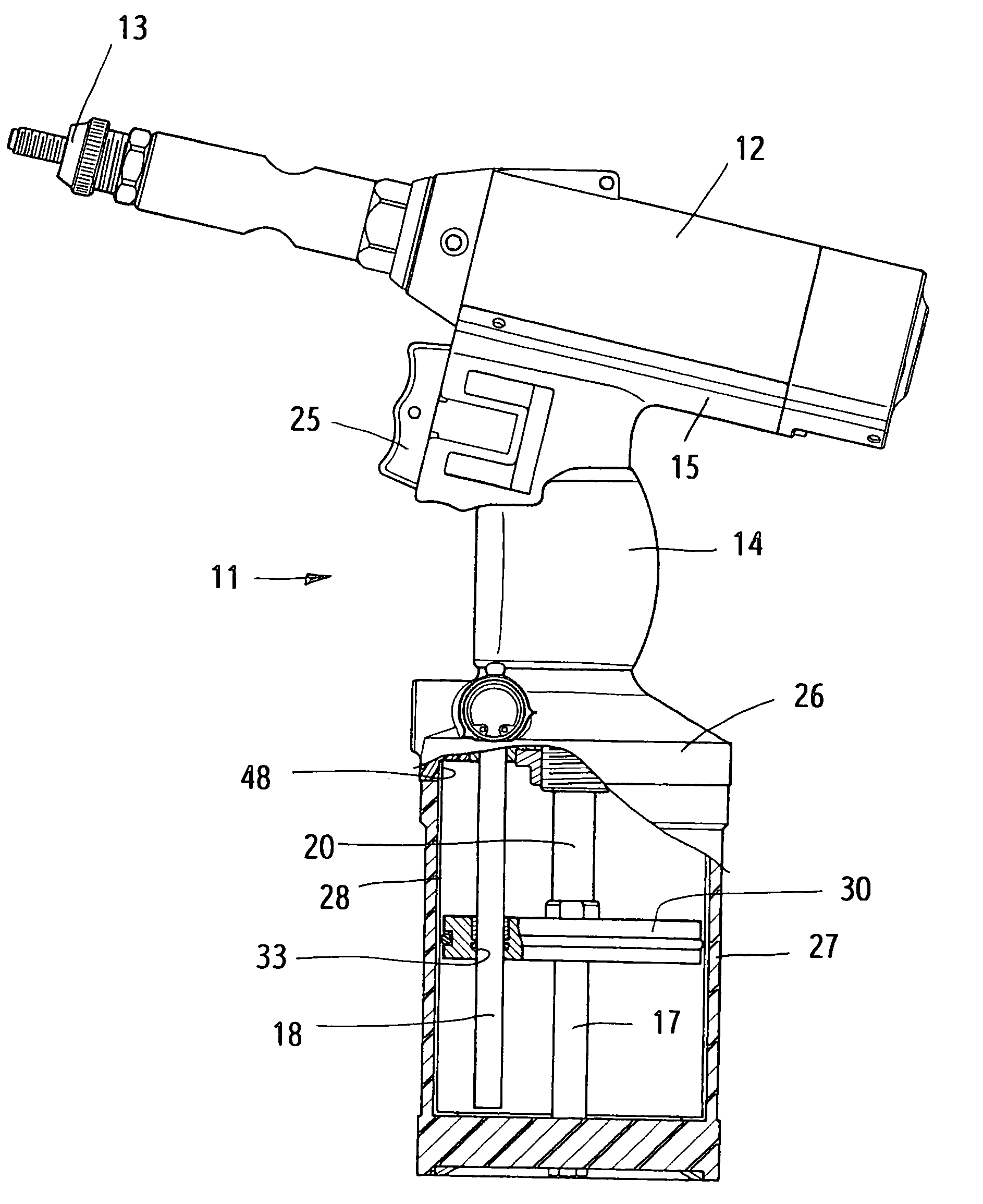
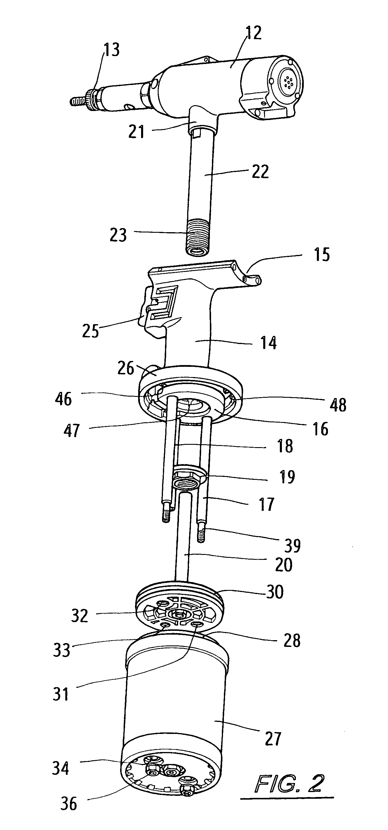
[0014]This invention relates to structure of a rivet gun; as shown in FIGS. 1, 2 and 4, the center of the handle 14 of rivet nut gun 11 is furnished with a cylindrical hole 24 for mounting a connecting rod 22 therein under the body 12; one end of the connecting rod 22 has threads 23, which extends into an inner surface 46 of a lid 26 under the handle 14; then, a fastening disk 16 with a round bar 17 is mounted in the inner surface 46, and then the cylindrical hole thereof is mounted to the threads 23, and is fastened in place with a nut 19; in that case, the body 12, the handle 14 and the fastening disk 16 are assembled together as one piece. The fastening disk 16 is mounted with round bars 17 to facilitate a pressure cylinder 27 be mounted in the inner surface 46 of the handle 14; after the round bars 17 penetrate through the cylindrical holes 34 in the bottom of the pressure cylinder 27, the round bars are fastened in place with nuts 36 so as to prevent the pressure cylinder 27 fr...


PUM

PropertyMeasurementUnit
Structureaaaaaaaaaa
Deformation enthalpyaaaaaaaaaa

Abstract

A structure of rivet nut gun having a body, a handle and a pressure cylinder. The top of the handle is furnished with a mounting base having a through cylindrical hole. The lower end of the handle is furnished with a base surface for mounting the fastening disk. The body has a connector mounted with a connecting rod to penetrate through the cylindrical hole of the handle. The fastening disk is fastened to one end of the connecting rod by a nut. The fastening disk is connected with two symmetrical screw rods, which penetrate through the piston and the pressure cylinder, and are fastened to the bottom of the pressure cylinder by two nuts respectively so as to have the piston cylinder fastened in place and to prevent the pressure cylinder from deformation during the rivet nut gun operating.

Description

BACKGROUND OF THE INVENTION[0001]1. Field of the Invention[0002]This invention relates to a rivet nut gun, and particularly to a structure of the rivet nut gun.[0003]2. Description of the Prior Art[0004]A conventional rivet nut gun usually comprises a body, a handle mounted under the body, and a pressure cylinder under the handle; the pressure cylinder includes a piston and a piston rod mounted in the cylindrical hole of the handle; through a pipe, a pressure air can flow into the lower space of the pressure cylinder to push the piston to move; then, a liquid in a hydraulic chamber will be pushed to provide a pressure to actuate the rivet nut gun; however, the parts and their assembling in the rivet nut gun are complex; the pressure cylinder is usually made of a pressure-proof metal, and is to be fastened under the handle; otherwise, a deformation would take place between the pressure cylinder and the handle as a result of riveting operation.SUMMARY OF THE INVENTION[0005]The prime o...

Claims


Application Information

Patent Timeline
IPC IPC(8): B21J15/06B21J15/22B25B27/00
CPCB21J15/105B21J15/22B25B27/0014Y10T29/53739Y10T29/53748
Inventor LIN, YU-CHING
Owner LIN YU CHING
Learn More