
Method and apparatus for programmable fluidic processing

a fluid processing and fluid technology, applied in the field of fluid processing, can solve the problems of large improvement room, mechanical devices using micro-scale implementations of traditional methods, and large failure risk of microchannels,

Inactive Publication Date: 2005-12-20
BOARD OF RGT THE UNIV OF TEXAS SYST
View PDF63 Cites 326 Cited by
  • Summary
  • Abstract
  • Description
  • Claims
  • Application Information

AI Technical Summary

Benefits of technology

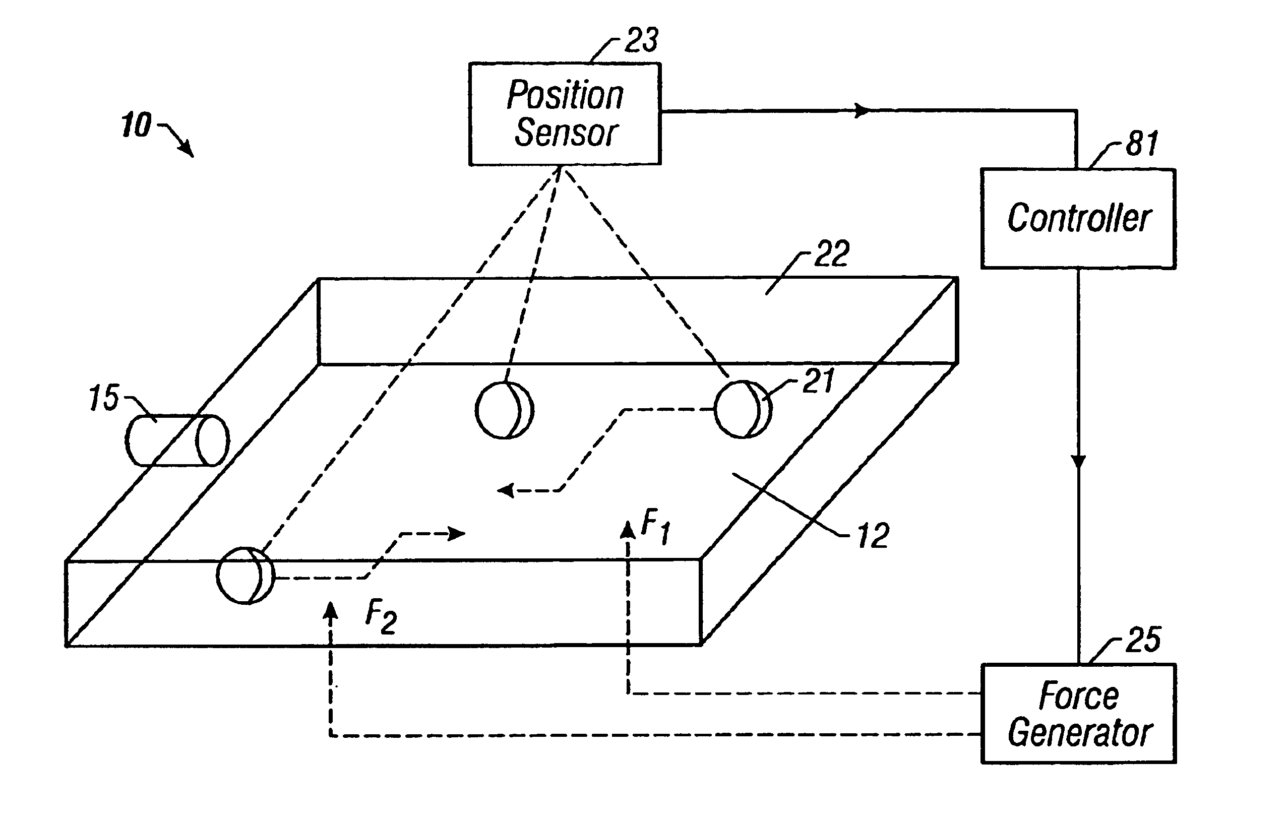
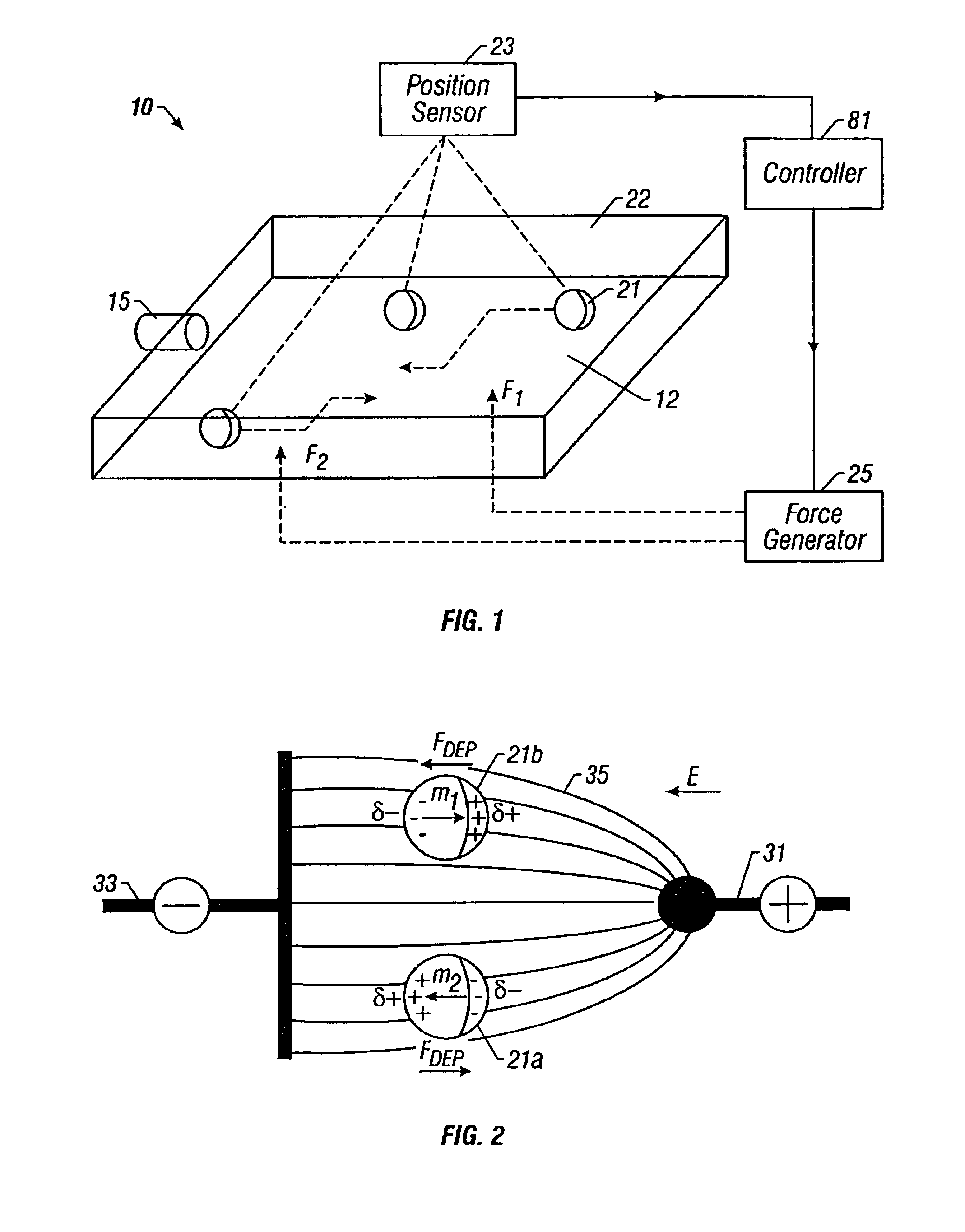
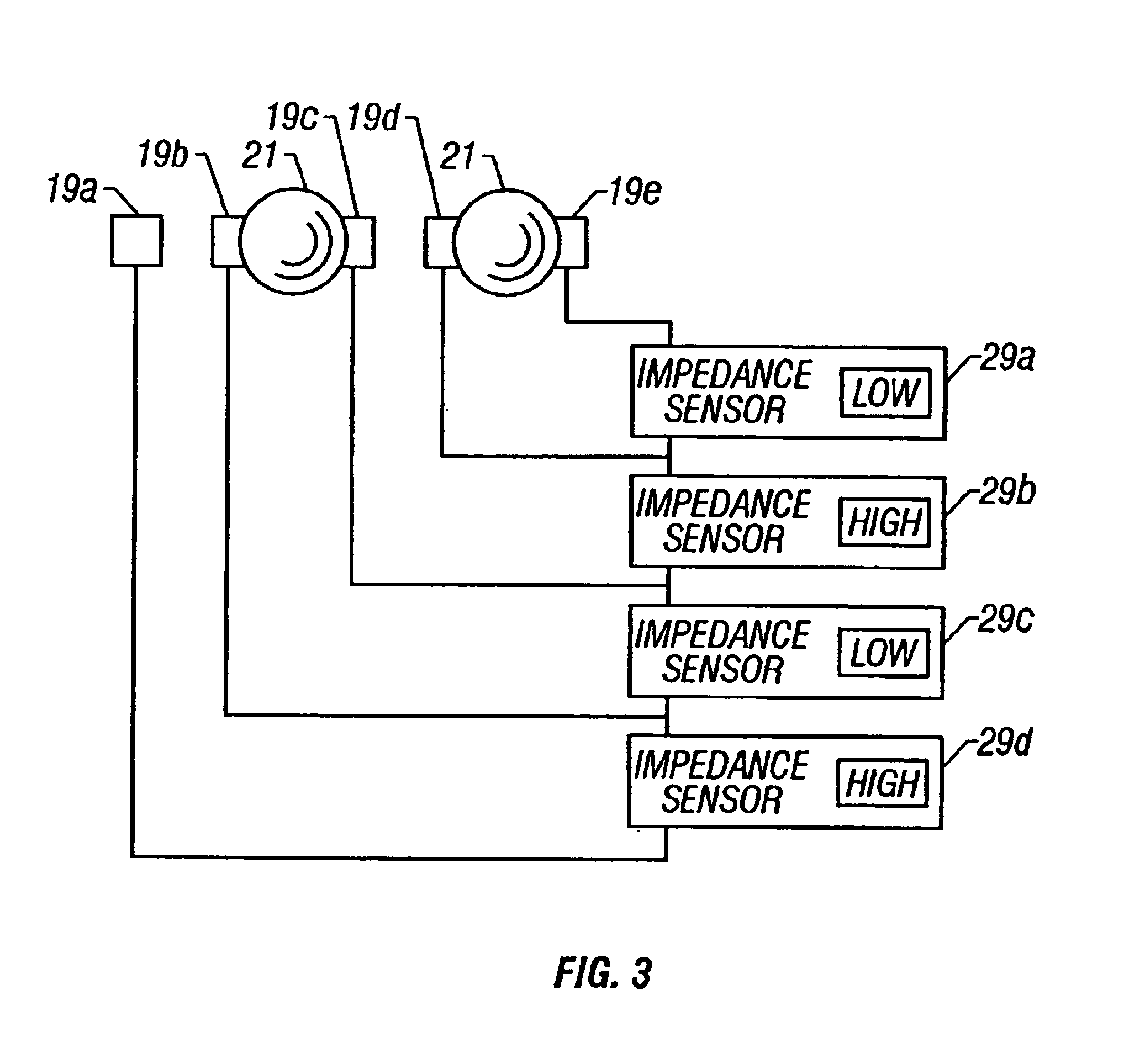
"The invention is an apparatus for manipulating packets of fluid or solid materials. The apparatus includes a reaction surface, an inlet port, means for generating a programmable manipulation force upon the packet, a position sensor, and a controller. The apparatus can programmably move the packet about the reaction surface along arbitrary paths. The position sensor can measure the position of the packet, and the controller can adjust the manipulation force accordingly. The apparatus can also include an outlet port to collect the packet, an array of driving electrodes to generate the manipulation force, and an array of impedance sensing electrodes to sense the position of the packet. The apparatus can also include a partitioning medium to suspend and compartmentalize other matter to form packets on a reaction surface. The technical effects of the invention include programmable manipulation of packets, improved control over their movement, and improved processing capabilities."

Problems solved by technology

While devices using micro-scale implementations of these traditional approaches may exhibit at least a degree of utility, vast room for improvement remains.
Mechanical devices, particularly when coupled to thin microchannels, may be prone to failure or blockage.
In particular, thin channels may become narrowed or partially-blocked due to buildup of channel contamination, which, in turn, may lead to mechanical failure of associated devices.
Current microfluidic devices also lack flexibility, for they rely upon a fixed pathway of microchannels.
With fixed pathways, devices are limited in the number and type of tasks they may perform.
Also, using fixed pathways makes many types of metering, transport, and manipulation difficult.
With traditional devices, it is difficult to partition one type of sample from another within a channel.
Although useful for determining particle dielectrophoretic properties, such a system is limited in application.
In particular, such a system does not allow for general fluidic processing involving various interactions, sometimes performed simultaneously, such as metering, mixing, fusing, transporting, division, and general manipulation of multiple reagents and reaction products.
In particular, such a system, utilizing attachment sites for certain binding entities is designed for particular applications and not for general fluidic processing of a variety of fluids.
Although useful for tasks such as separation, room for improvement remains in that such devices are not well suited for performing a wide variety of fluidic processing interactions on a wide variety of different materials.
While perhaps useful for facilitating certain interactions between many particles of different types, the method is not well suited for general fluidic processing.
Although useful for inducing certain chemical reactions, its flexibility is limited, and it does not allow for general, programmable fluidic processing.
Any problems or shortcomings enumerated in the foregoing are not intended to be exhaustive but rather are among many that tend to impair the effectiveness of previously known processing techniques.
Other noteworthy problems may also exist; however, those presented above should be sufficient to demonstrated that apparatus and methods appearing in the art have not been altogether satisfactory.

Method used


Image

  • Method and apparatus for programmable fluidic processing
  • Method and apparatus for programmable fluidic processing
  • Method and apparatus for programmable fluidic processing

Examples


example 1

[0125]Aqueous materials have been compartmentalized to form packets using hydrophobic liquids as a partitioning medium. Partitioning mediums so used have included decane, bromodocane, mineral oil, and 3 in 1™ oil. Packets have been formed by briefly sonicating about 3 milliliters of the hydrophobic liquid to which had been added 20 to 50 microliters of aqueous medium. Aqueous media tested have included deionized water, tap water (electrical conductivity of about 40 mS / m) and phosphate buffered saline (PBS) solution.

example 2

[0126]Aqueous packets suspended in mineral oil, bromodoecane and 3 in 1™ oil have been collected by dielectrophoresis by applying sinusoidal signals to gold-on-glass electrode arrays having 20, 80 and 160 micron spacing, respectively. The 20-micron electrode array consisted of parallel line electrodes (20 microns in width and spacing). The 80 and 160 micron electrode arrays were of the interdigitated, castellated geometries. Aqueous packets were collected at electrode edges or tips when AC voltage signals between 100 Hz and 20 MHz were applied. Applied voltages were from 10 to 100 V peak-to-peak. The formation of pearl-chains of water packets has also been observed.

example 3

[0127]Aqueous packets in hydrophobic suspension have been brought together and fused under the influence of dielectrophoretic forces on the same electrode arrays used in Example 2.


PUM

PropertyMeasurementUnit
diameteraaaaaaaaaa
diameteraaaaaaaaaa
distanceaaaaaaaaaa

Abstract

A method and apparatus for microfluidic processing by programmably manipulating a packet. A material is introduced onto a reaction surface and compartmentalized to form a packet. A position of the packet is sensed with a position sensor. A programmable manipulation force is applied to the packet at the position. The programmable manipulation force is adjustable according to packet position by a controller. The packet is programmably moved according to the programmable manipulation force along arbitrarily chosen paths.

Description

[0001]This is a continuation of application Ser. No. 09 / 249,955, filed Feb. 12, 1999, which is now U.S. Pat. No. 6,294,063 on Nov. 14, 2003.BACKGROUND OF THE INVENTION[0002]1. Field of the Invention[0003]The present invention relates generally to fluidic processing and, more particularly, to a method and apparatus for programmably manipulating and interacting one or more compartmentalized packets of material on a reaction surface.[0004]2. Description of Related Art[0005]Chemical protocols often involve a number of processing steps including metering, mixing, transporting, division, and other manipulation of fluids. For example, fluids are often prepared in test tubes, metered out using pipettes, transported into different test tubes, and mixed with other fluids to promote one or more reactions. During such procedures, reagents, intermediates, and / or final reaction products may be monitored, measured, or sensed in analytical apparatus. Microfluidic processing generally involves such ...

Claims


Application Information

Patent Timeline
Patent Type & Authority Patents(United States)
IPC IPC(8): B01D57/02B01F13/00B01J19/00B03C5/00B01L3/00B03C5/02
CPCB01F13/0076G01N27/44773B01L3/502715B01L3/502761B01L3/502792B03C5/005B03C5/024B03C5/026B03C5/028G01N27/447B01L2200/143B01L2300/089B01L2400/0421B01L2400/0424B01L2400/0454B01F2215/0404B01F33/3031
Inventor BECKER, FREDERICK F.GASCOYNE, PETERWANG, XIAOBOVYKOUKAL, JODYDE GASPERIS, GIOVANNI
Owner BOARD OF RGT THE UNIV OF TEXAS SYST
Learn More