
Folding handle assembly for a vehicle

a technology for a vehicle and a handle is applied in the field of assist handles or rails for recreational vehicles, which can solve the problems of handles being inadvertently moved or pushed out of their in use position to their own position,

Inactive Publication Date: 2005-12-13
ASC INDS
View PDF39 Cites 39 Cited by
  • Summary
  • Abstract
  • Description
  • Claims
  • Application Information

AI Technical Summary

Benefits of technology

[0004]The present invention provides a handle assembly for a vehicle, such as a recreational vehicle or the like, that provides a positive stop or lock to positively retain the handrail or handle in either a storage or stored position, where the handrail is positioned along the side of the vehicle, or an in use position, where the handrail extends outward from the vehicle for a user to grasp while entering or exiting the vehicle. The present invention may also provide an illumination source at the handle to illuminate the handle or handrail to assist a person in seeing and using the handrail in darkened conditions, such as night time conditions or the like.
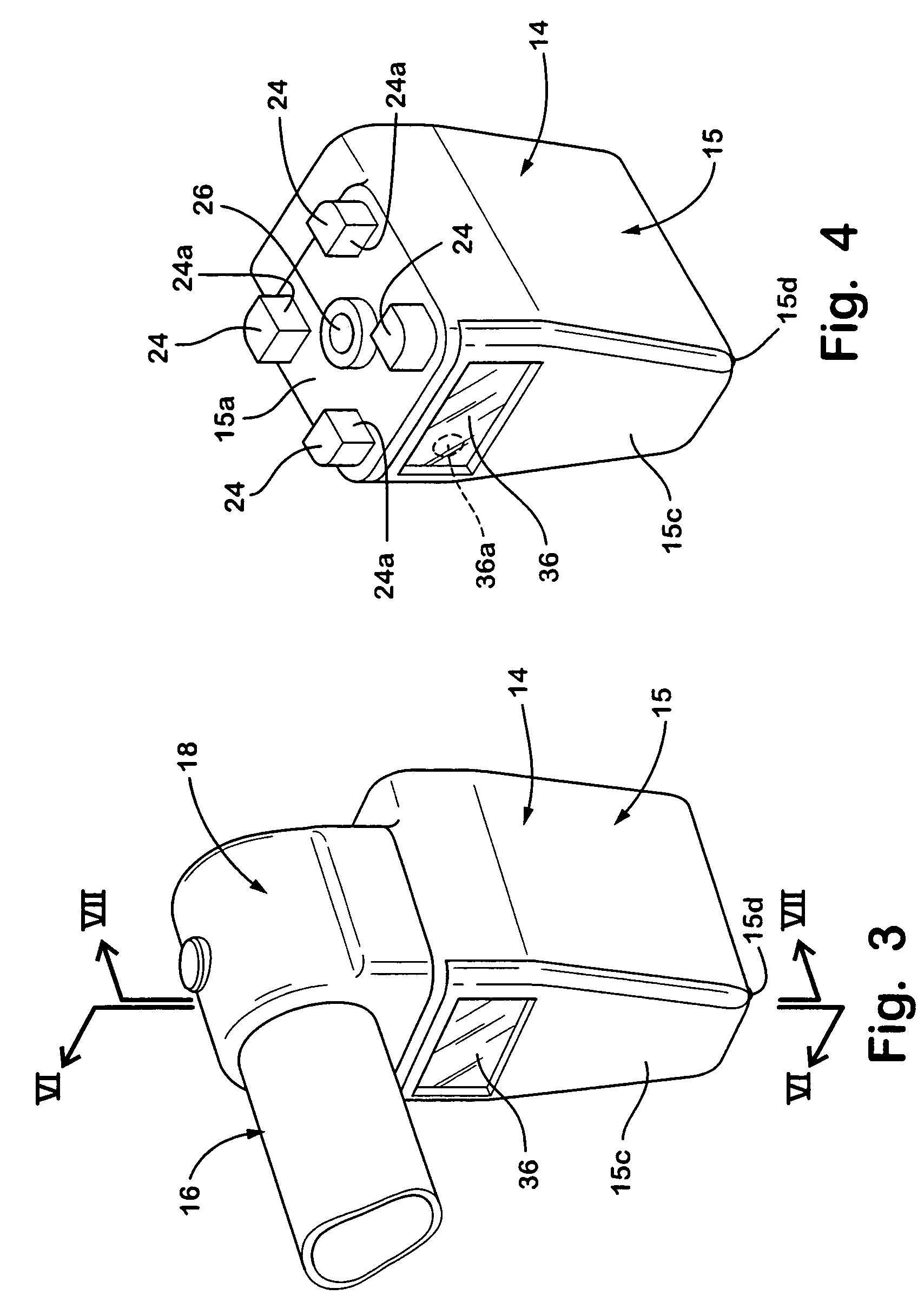
[0005]According to an aspect of the present invention, a handle assembly for mounting to a surface of a vehicle includes a handrail and a bracket. The handrail is formed of a tubular member and has a curved cross section. The handrail has an end cap that is joined with the tubular member and that is selectively engagable with the bracket in first and second positions relative to the bracket. The handrail is selectively movable to disengage the end cap from the bracket and is pivotable when the end cap is disengaged from the bracket to move the end cap between the first position, where the handrail is positioned along the surface of the vehicle, and the second position, where the handrail extends outward from the surface of the vehicle. The end cap limits pivotal movement of the handrail when the end cap is engaged with the bracket and the handrail is substantially positively fixed or retained in the first or second position relative to the bracket when the end cap is engaged with the bracket.
[0008]According to another aspect of the present invention, a handle assembly for mounting to a surface of a vehicle includes a handrail and a bracket. The handrail has an end portion that has a first engaging face and the bracket has a second engaging face. The handrail is pivotable relative to the bracket about a pivot axis. The first and second engaging faces are selectively engagable in first and second positions. The handrail is selectively movable to disengage the first engaging face from the second engaging face and is pivotable about the pivot axis when the first and second engaging faces are disengaged to move the handrail between the first position, where the handrail is positioned along the surface of the vehicle, and the second position, where the handrail extends outward from the surface of the vehicle. The first and second engaging faces are generally parallel to the pivot axis to substantially positively retain the handrail relative to the bracket when the engaging faces are engaged.
[0010]Therefore, the handle assembly of the present invention provides a positive stop or locking mechanism to substantially positively retain the handrail in either the storage position or in use position relative to the bracket affixed to the wall of the vehicle. The handle assembly of the present invention thus limits or substantially precludes inadvertent movement of the handrail from one position to the other. In order to move the handle to the in use or to the storage position, the handrail may be raised upward or otherwise moved along its pivot axis to disengage the end of the handrail from the bracket. If the handrail is pushed sideways without such raising or movement, the handrail and bracket function to limit or substantially preclude pivotal movement of the handrail relative to the bracket. Also, the handle assembly may include a light or illumination source to provide illumination to the handrail to assist a person in using the handrail in darkened conditions.

Problems solved by technology

The handles thus may be inadvertently moved or pushed out of their in use position to their stored position, such as if a person leans against the handles or the like.

Method used


Image

  • Folding handle assembly for a vehicle
  • Folding handle assembly for a vehicle
  • Folding handle assembly for a vehicle

Examples


Embodiment Construction

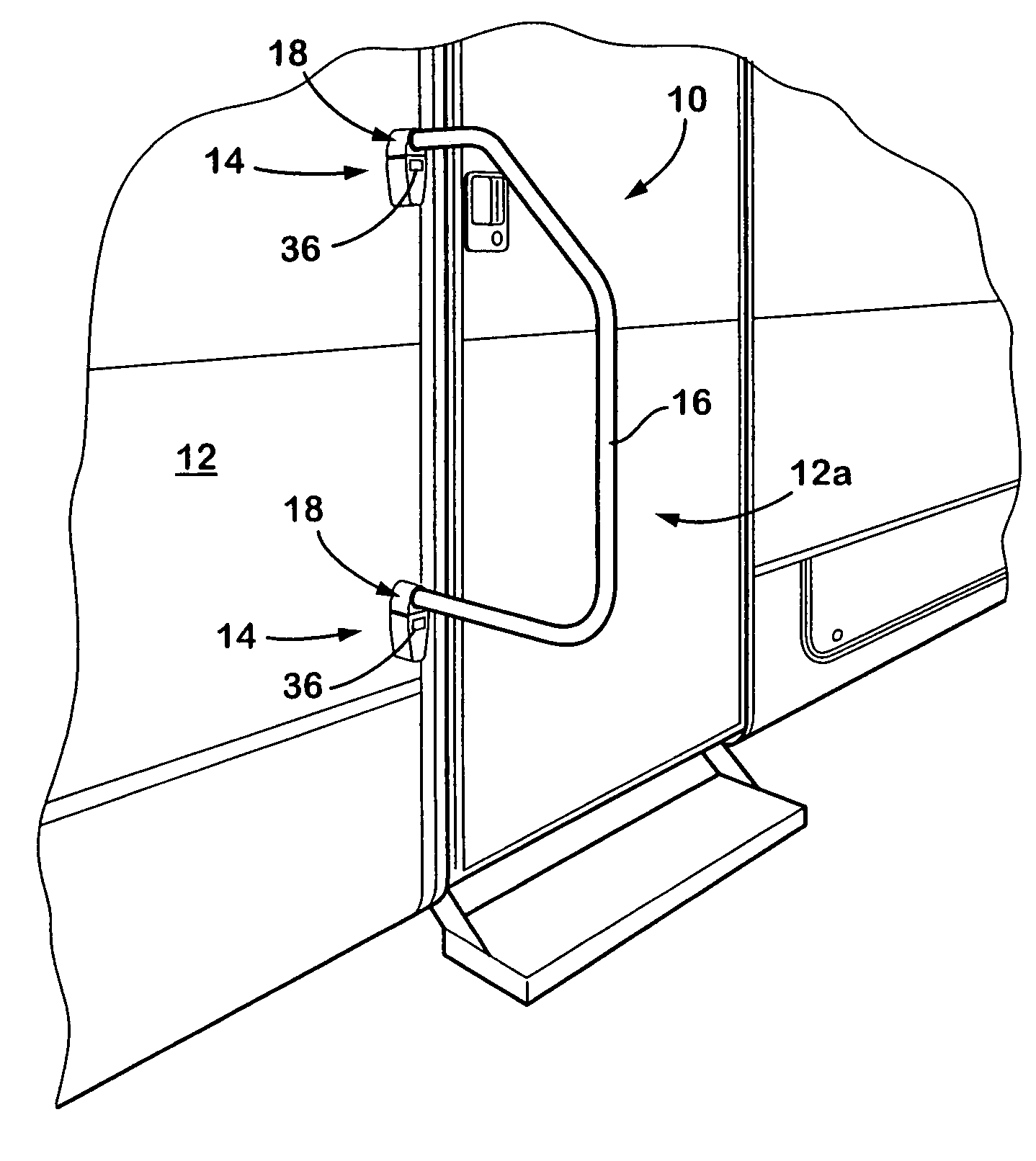
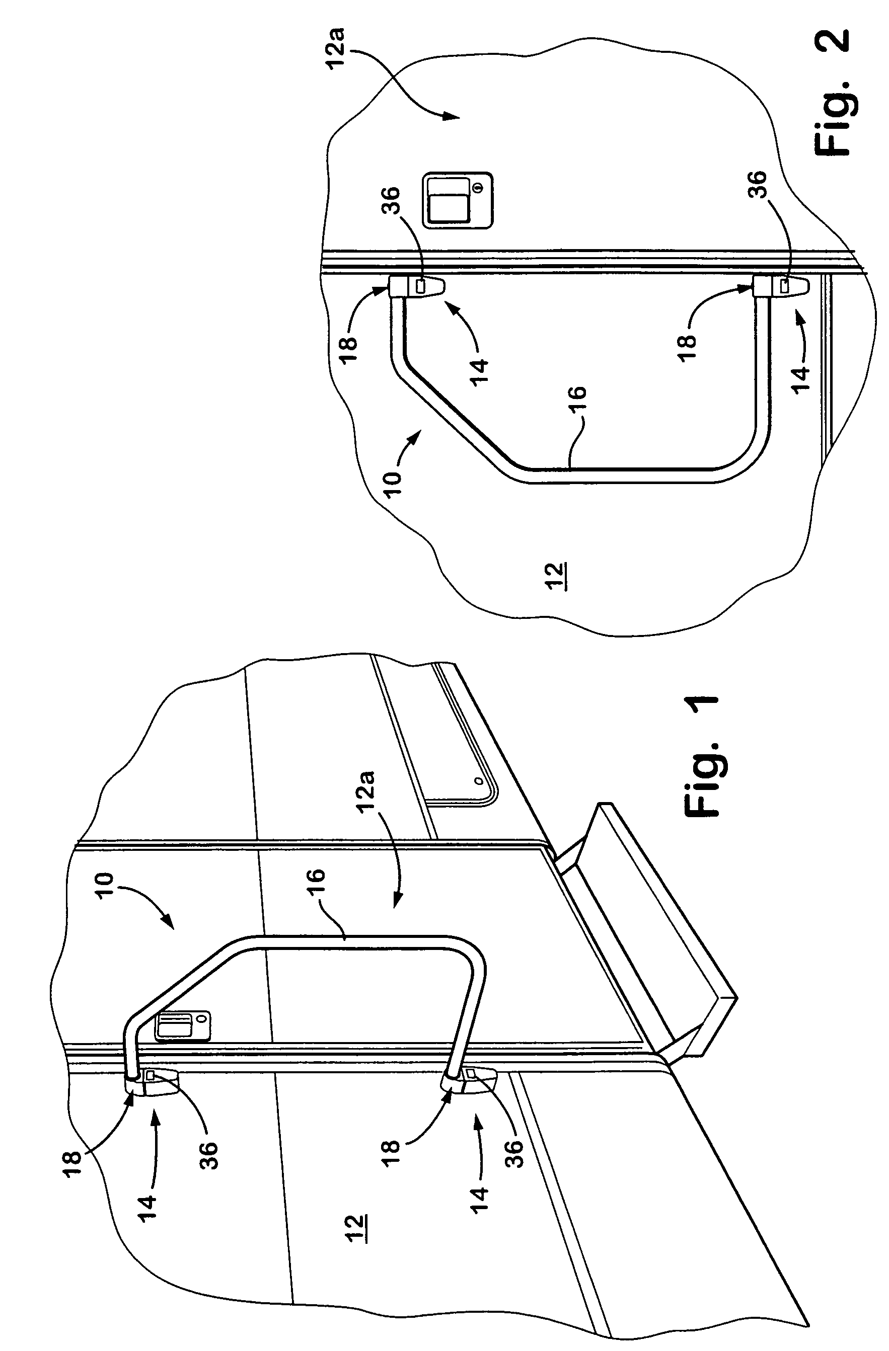
[0026]Referring now to the drawings and the illustrative embodiment depicted therein, a fold away handrail or handle assembly 10 is mountable to a side or surface of a vehicle 12 adjacent to a door other opening 12a in the vehicle 12 (FIGS. 1 and 2). The handle assembly 10 includes a pair of brackets 14 and a handrail or handle 16 pivotally mounted at each end 16a to brackets 14. As can be seen in FIGS. 1 and 2, handle 16 is selectively pivotable between an in use position (FIG. 1) where the handle extends outwardly from the side of the vehicle for a person to grasp and use while exiting or entering the vehicle, and a fold away or stored position (FIG. 2), where the handle is folded along the side of the vehicle when it is not in use. The ends 16a of handle 16 positively engage brackets 14 to positively retain the handle in either the in use position or the stored position, and limit or substantially preclude inadvertent moving or pivoting of the handle to the other position, as dis...


PUM


Abstract

A handle assembly that pivotally mounts a handle adjacent to an opening of a vehicle includes a bracket and an end portion or cap portion of a handle. The end portion and bracket engage one another to substantially secure the handle in either an in use position or a storage position. The end portion and bracket include projections and correspondingly formed recesses that engage one another to limit or substantially preclude pivotal movement of the handle without first raising the handle to disengage the handle and cap portion from the bracket. The handle assembly may include an illumination source to provide illumination of the handle in low lighting conditions.

Description

FIELD OF THE INVENTION[0001]The present invention relates generally to assist handles or rails for recreational vehicles and the like and, more particularly, to a fold away assist handle or rail assembly which is mountable to a side of a recreational vehicle or the like.BACKGROUND OF THE INVENTION[0002]Fold away assist rails or handles are known or are mountable to a side of a recreational vehicle or the like via securing brackets to the vehicle with suitable fasteners. The handle or railing is foldable between a stored position, where the handle is positioned generally along a side of the vehicle, and an in use position, where the handle extends outwardly from the vehicle for a person to grasp the handle as they are entering or leaving the recreational vehicle. The handle is pivotally mounted to a pair of brackets via a pivot pin at each end of the handle. The brackets are mounted to or installed at the side of the vehicle. Typically, the brackets are biased toward the storage or i...

Claims


Application Information

Patent Timeline
IPC IPC(8): B60J7/00B60N3/02B60Q1/26
CPCB60N3/023B60N3/026B60Q1/2669E05B1/0015Y10T16/458E05B83/44F21W2111/08
Inventor MACRI, GREGORY G.LARK, II, JAMES D.
Owner ASC INDS
Learn More