Eureka AIR delivers breakthrough ideas for toughest innovation challenges, trusted by R&D personnel around the world.

Fishing rod and butt grip for such rods

a technology of fishing rods and butt grips, which is applied in the field of fishing rods, can solve the problems of increasing the production cost of fishing rods, reducing the sensitivity of users responding to the vital vibration of fish, and reducing the interest of users in fishing

Inactive Publication Date: 2005-12-13
KIM MYUNG KWON
View PDF6 Cites 54 Cited by
  • Summary
  • Abstract
  • Description
  • Claims
  • Application Information

AI Technical Summary

Benefits of technology

[0011]Accordingly, the present invention has been made keeping in mind the above problems occuring in prior art, and an object of the present invention is to provide a fishing rod, which allows a fishing rod to feel light, soft and comfortable when a user grasps the butt grip of the rod while fishing.
[0012]Another object of the present invention is to provide a fishing rod, which directly transmits vital vibration of a fish taking a bait or caught by the hook to the hand of a user holding the butt grip, thus allowing the user to have a thrilling and agreeable feeling while fishing, and doubling a user's interest in fishing.
[0013]A further object of the present invention is to provide a butt grip for fishing rods, which is made of a synthetic resin capable of improving productivity of the butt grips and reducing the production cost of the grips, and thereby providing fishing rods having moderate prices.

Problems solved by technology

This reduces a user's interest in fishing.
This reduces sensitivity of a user responding to the vital vibration of a fish while fishing.
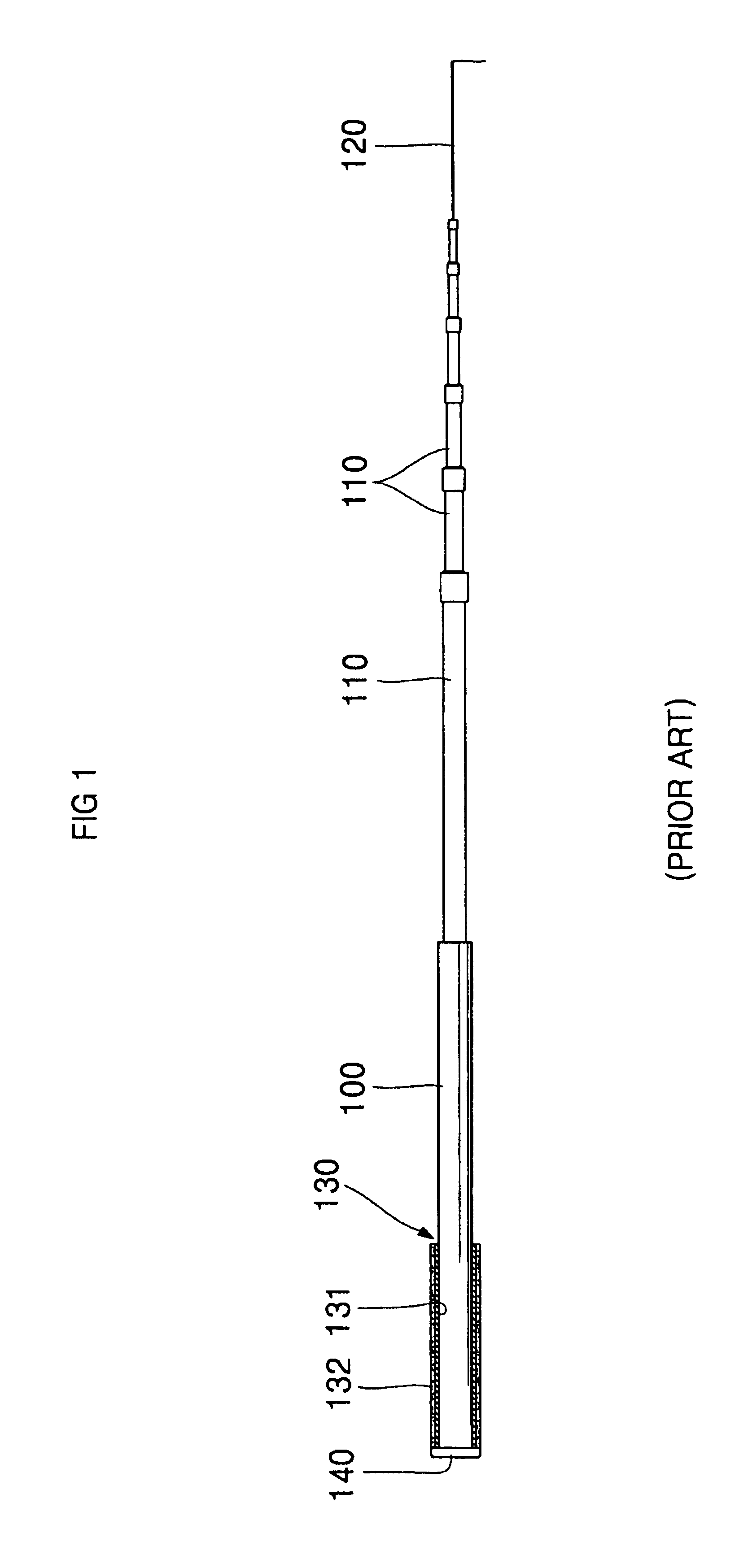
Furthermore, the conventional butt grip 130 of a fishing rod is made of expensive materials, such as sponge, cork, or pulp, thus increasing the production cost of fishing rods.
This forces users of fishing rods to pay much money for purchasing the rods.

Method used


Image

  • Fishing rod and butt grip for such rods
  • Fishing rod and butt grip for such rods
  • Fishing rod and butt grip for such rods

Examples


Embodiment Construction

[0025]Reference now should be made to the drawings, in which the same reference numerals are used throughout the different drawings to designate the same or similar components.

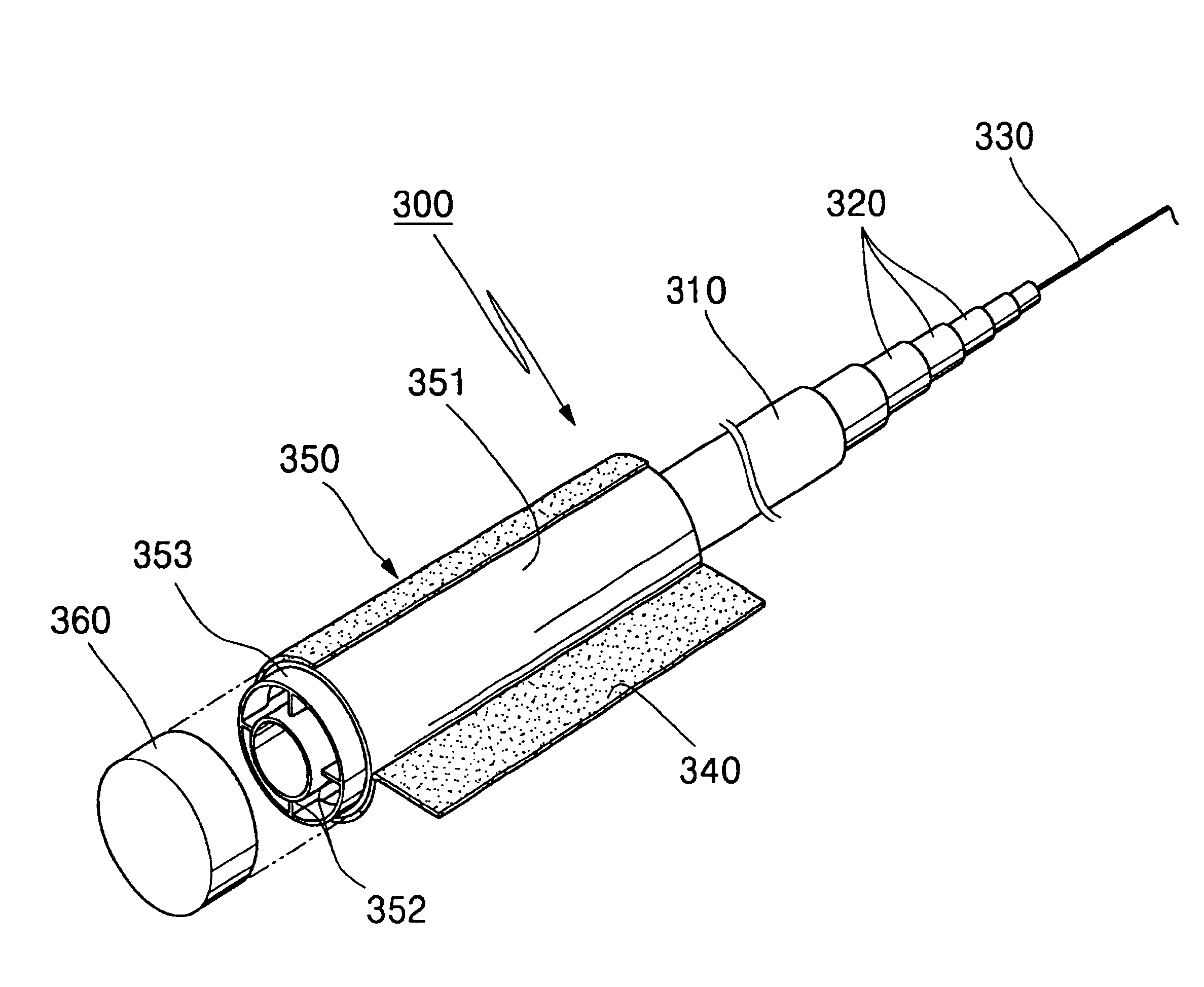
[0026]FIG. 3 is an exploded perspective view of a fishing rod in accordance with the primary embodiment of the present invention. FIG. 4 is a sectional view of a butt grip of the fishing rod. As shown in the drawings, the fishing rod 300 of this invention comprises a hollow cylindrical butt pipe 310, the length and inner diameter of which are determined by the number of joints of the fishing rod, and a plurality of hollow cylindrical sections 320, the number of which is determined in accordance with the number of joints. The hollow sections 320 are gradually reduced in their inner diameters such that the innermost section near the butt pipe 310 has the largest diameter and the outermost section remote from the pipe 310 has the smallest diameter. All the sections 320 are sequentially jointed together to form a ...


PUM


Abstract

The fishing rod of this invention includes a hollow cylindrical butt pipe, and a plurality of hollow cylindrical sections sequentially jointed together to form a telescopically retractable structure jointed to the butt pipe such that the sections are sequentially retracted into the butt pipe. A tip rod is mounted to the end of the outermost one of the sections remote from the butt pipe. A butt grip is fitted over the butt pipe, and consists of a hollow cylindrical tube opened at both ends thereof. A plurality of radial support ribs are formed on the inner surface of the tube while being directed in radial directions and spaced apart from each other at regular intervals. When the butt grip is fitted over the butt pipe, the external surface of the butt pipe is brought into close contact with the inside edges of the radial support ribs. The butt grip directly transmits vital vibrations of a fish taking a bait or caught by the hook to the hand of a user holding it, thus allowing the user to have a thrilling and agreeable feeling while fishing, and doubling a user's interest in fishing.

Description

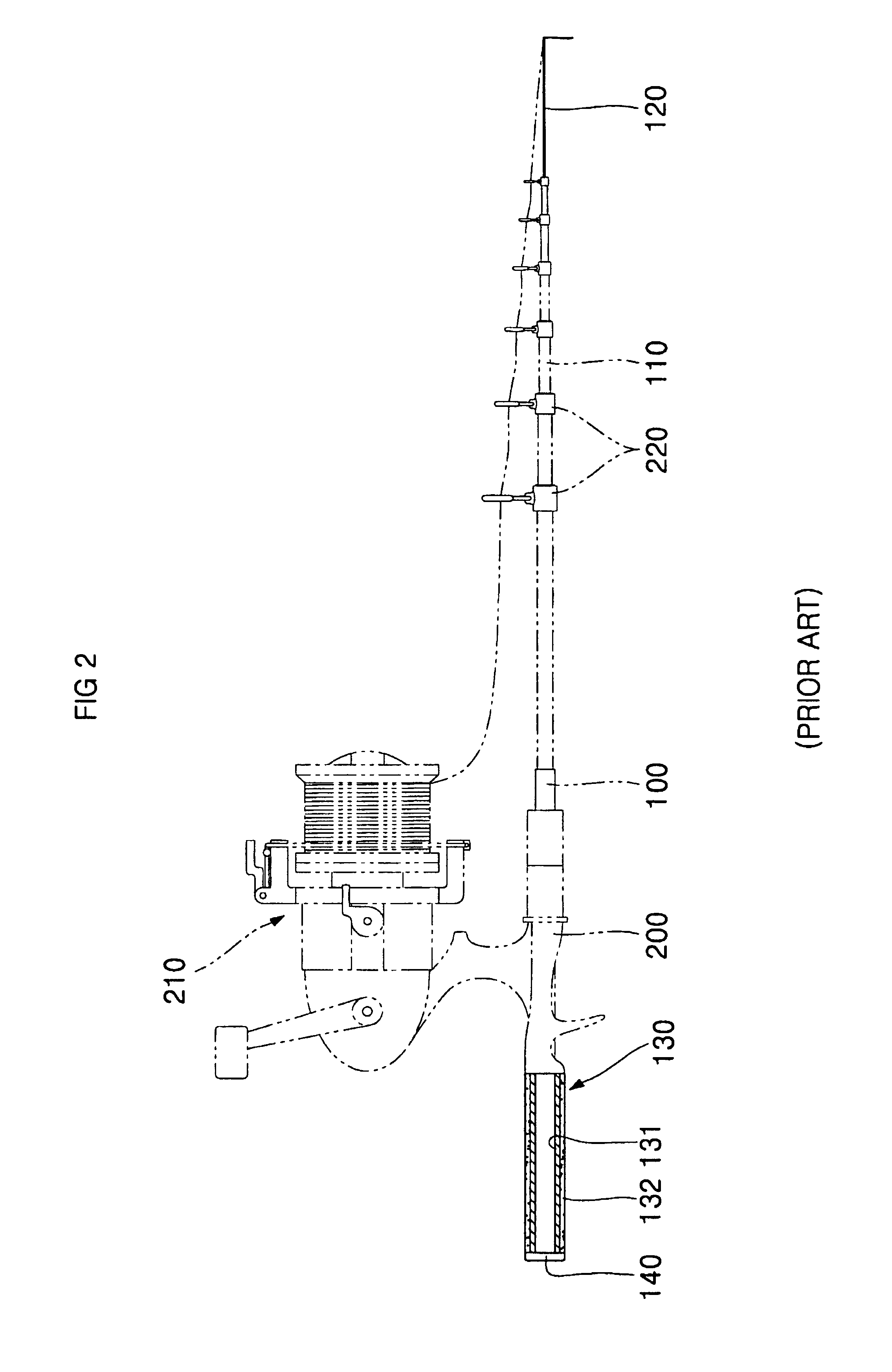
BACKGROUND OF THE INVENTION[0001]1. Field of the Invention[0002]The present invention relates, in general, to fishing rods and, more particularly, to a butt grip for such fishing rods, which allows a fishing rod to feel light, soft and comfortable when it is grasped by a user while fishing, and directly transmits vital vibrations of a fish taking a bait or caught by the hook to the hand of a user holding it, thus allowing the user to have a thrilling and agreeable feeling while fishing, and doubling a user's interest in fishing.[0003]2. Description of the Prior Art[0004]As well known to those skilled in the art, fishing rods have been classified into three types: general rods without having any reels, fly rods with fly reels, and spinning rods with spinning reels. The size of fishing rods has been typically expressed by the number of joints of the rods. FIG. 1 shows the structure of a conventional general rod. As shown in the drawing, the conventional general rod comprises a butt pi...

Claims


Application Information

Patent Timeline
Patent Type & Authority Patents(United States)
IPC IPC(8): A01K87/00A01K87/02A01K87/08
CPCA01K87/025A01K87/08A01K87/002
Inventor KIM, MYUNG KWON
Owner KIM MYUNG KWON
Why Eureka
Eureka Blog
Learn More