Eureka AIR delivers breakthrough ideas for toughest innovation challenges, trusted by R&D personnel around the world.

System and method for stereo conferencing over low-bandwidth links

a low-bandwidth link and system technology, applied in the field of packet voice conferencing, can solve the problems of roughly double the required bandwidth and codec unusable for the conference, and achieve the effects of satisfying sound quality, increasing bandwidth, and tangible benefits

Inactive Publication Date: 2005-12-06
CISCO TECH INC
View PDF4 Cites 102 Cited by
  • Summary
  • Abstract
  • Description
  • Claims
  • Application Information

AI Technical Summary

Benefits of technology

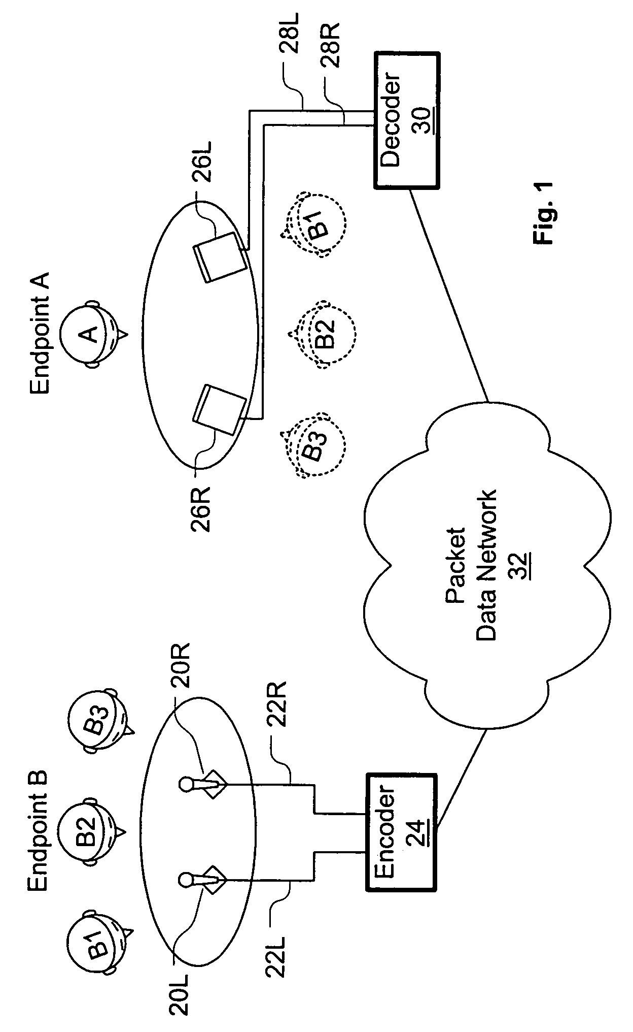
[0006]The present disclosure introduces new encoding / decoding systems and methods for packet voice conferencing. The systems and methods allow a pseudo-stereo packet voice conference to be conducted with only a negligible increase in bandwidth as compared to a monophonic packet voice conference. In addition to providing a generally more satisfying sound quality than monophonic conferencing, these systems and methods can provide a more tangible benefit when one end of a conference has multiple participants—the ability of the listener to receive a unique directional cue for each speaker on the other end of the conference. Moreover, because only a negligible increase in bandwidth over a monophonic conference is required, the present invention allows the advantages of stereo to be enjoyed over any data link that can support a monophonic conferencing data rate.

Problems solved by technology

In some instances, the sustained bandwidth required by a given codec may approach or exceed the data link bandwidth at one of the endpoints, making that codec unusable for that conference.
Unfortunately, either of these audio quality improvements roughly doubles the required bandwidth for a voice conference.

Method used


Image

  • System and method for stereo conferencing over low-bandwidth links
  • System and method for stereo conferencing over low-bandwidth links
  • System and method for stereo conferencing over low-bandwidth links

Examples


Embodiment Construction

[0020]In the following description, a packet voice conferencing system exchanges real-time audio conferencing signals with at least one other packet voice conferencing system in packet format. Such a system can be located at a conferencing endpoint (i.e., where a human conferencing participant is located), in an intermediate Multipoint Conferencing Unit (MCU) that mixes or bridges signals from conferencing endpoints, or in a voice gateway that receives signals from a remote endpoint in non-packet format and converts those signals to packet format. MCUs and voice gateways can typically handle more than one simultaneous conference. Note that not every endpoint in a packet voice conference need receive and transmit packet-formatted signals, as MCUs and voice gateways can provide conversion for non-packet endpoints. Such systems are also not limited to voice signals only—other audio signals can be transmitted as part of the conference, and the system can simultaneously transmit packet v...


PUM


Abstract

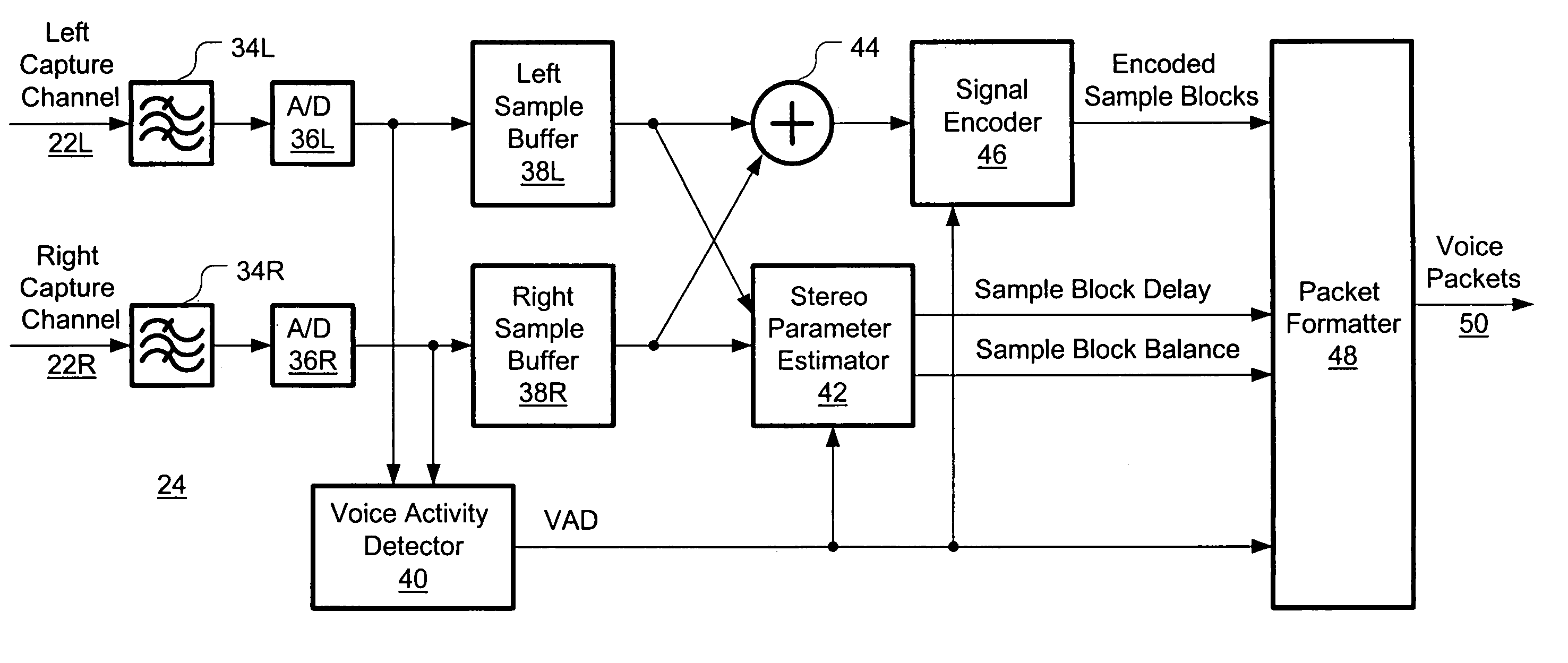
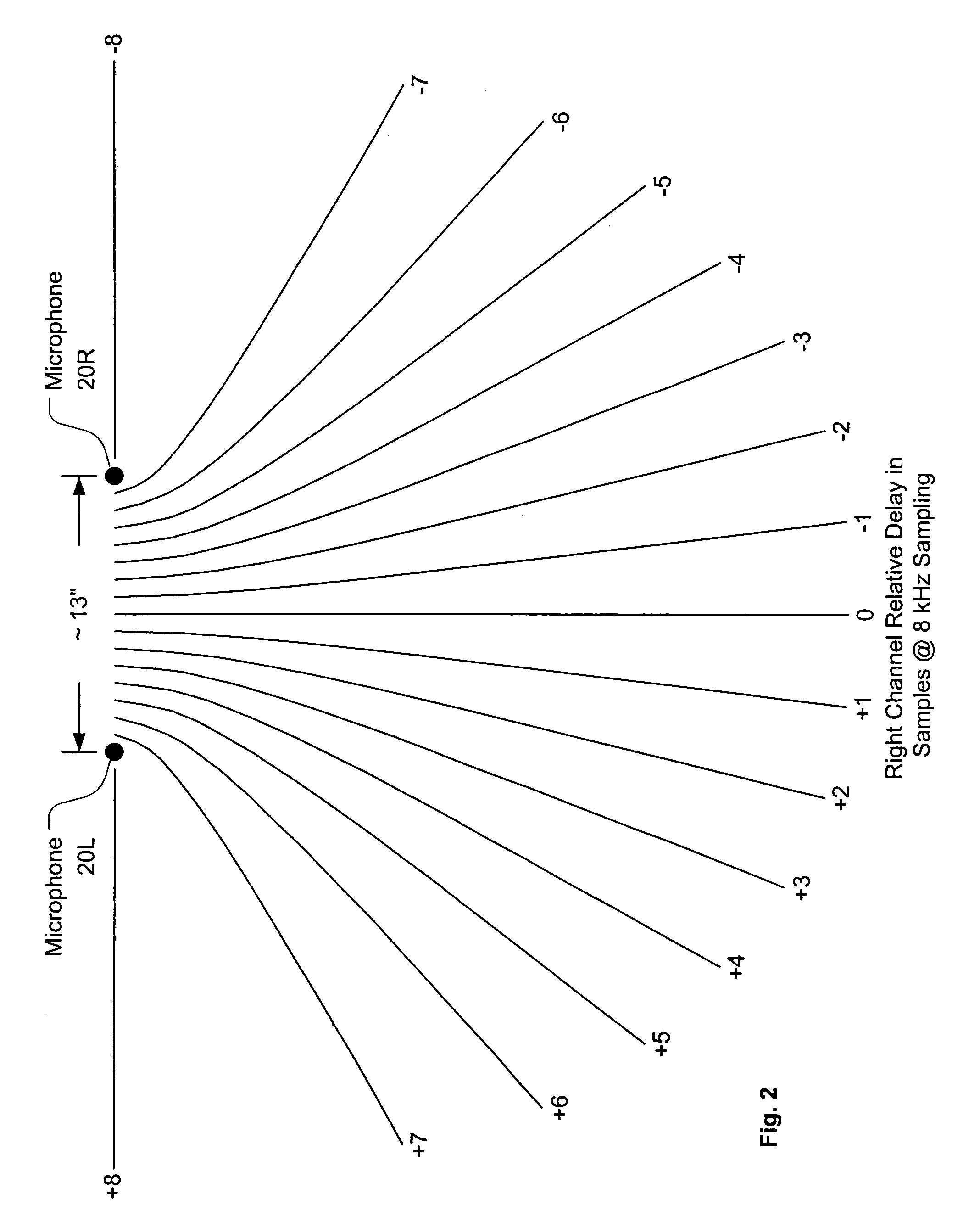
Systems and methods are disclosed for packet voice conferencing. An encoding system accepts two sound field signals, representing the same sound field sampled at two spatially-separated points. The relative delay between the two sound field signals is detected over a given time interval. The sound field signals are combined and then encoded as a single audio signal, e.g., by a method suitable for monophonic VoIP. The encoded audio payload and the relative delay are placed in one or more packets and sent to a decoding device via the packet network. The decoding device uses the relative delay to drive a playout splitter—once the encoded audio payload has been decoded, the playout splitter creates multiple presentation channels by inserting the transmitted relative delay in the decoded signal for one (or more) of the presentation channels. The listener thus perceives a speaker's voice as originating from a location related to the speaker's physical position at the other end of the conference. An advantage of these embodiments is that a pseudo-stereo conference can be conducted with virtually the same bandwidth as a monophonic conference.

Description

FIELD OF THE INVENTION[0001]This present invention relates generally to packet voice conferencing, and more particularly to systems and methods for packet voice stereo conferencing without explicit transmission of two voice channels.BACKGROUND OF THE INVENTION[0002]Packet-switched networks route data from a source to a destination in packets. A packet is a relatively small sequence of digital symbols (e.g., several tens of binary octets up to several thousands of binary octets) that contains a payload and one or more headers. The payload is the information that the source wishes to send to the destination. The headers contain information about the nature of the payload and its delivery. For instance, headers can contain a source address, a destination address, data length and data format information, data sequencing or timing information, flow control information, and error correction information.[0003]A packet's payload can consist of just about anything that can be conveyed as dig...

Claims


Application Information

Patent Timeline
IPC IPC(8): H04M9/08H04R27/00H04S5/00
CPCH04R27/00G10L19/008
Inventor SHAFFER, SHMUELKNAPPE, MICHAEL E.
Owner CISCO TECH INC
Why Eureka
Eureka Blog
Learn More