
Connector adapter with memory function unit

a technology of memory function and connector adapter, which is applied in the direction of coupling device connection, optical element, instruments, etc., can solve the problems of affecting the convenience of operation using control information of this type, affecting the convenience of operation, and erroneous understanding or erroneous input of control information

Inactive Publication Date: 2005-12-06
TOKYO TSUSHINKI INDS
View PDF2 Cites 173 Cited by
  • Summary
  • Abstract
  • Description
  • Claims
  • Application Information

AI Technical Summary

Benefits of technology

[0015]An object of the present invention is to provide a connector adapter for coupling to a connector plug, which is provided with memory function unit for control information, thereby capable of checking within a high speed connection state of the connector adapter and the connector plug.

Problems solved by technology

In this case, mistake such as erroneous understanding or erroneous inputting of control information shall be occasionally occurred, if letters are employed as the control information, since an operator performs the inputting operations in reading of the letters of control information.
However, if the read-in operation is overlooked at a working operation step, reliable control of this working operation step cannot be performed.
In this case where optical connectors carrying control information of these label and tape are accumulated on a distributing frame in a real application circumstance, the label itself becomes considerable obstacle for freely manipulation so that the convenience of operation using the control information of this type is disturbed.
Furthermore, if material of the label and the tape is of paper, the label and the tape may be damaged, so that the control information cannot be recognized and then controlled.
Moreover, in a case where the connecter plug 4 is not completely inserted in the connector adapter 2 (i.e.: incomplete insertion), there will occur undesirable troubles, such as intermittent disconnection or interruption.

Method used


Image

  • Connector adapter with memory function unit
  • Connector adapter with memory function unit
  • Connector adapter with memory function unit

Examples


Embodiment Construction

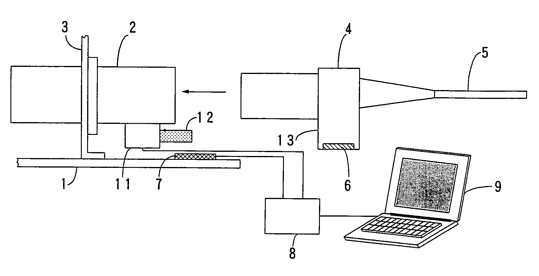
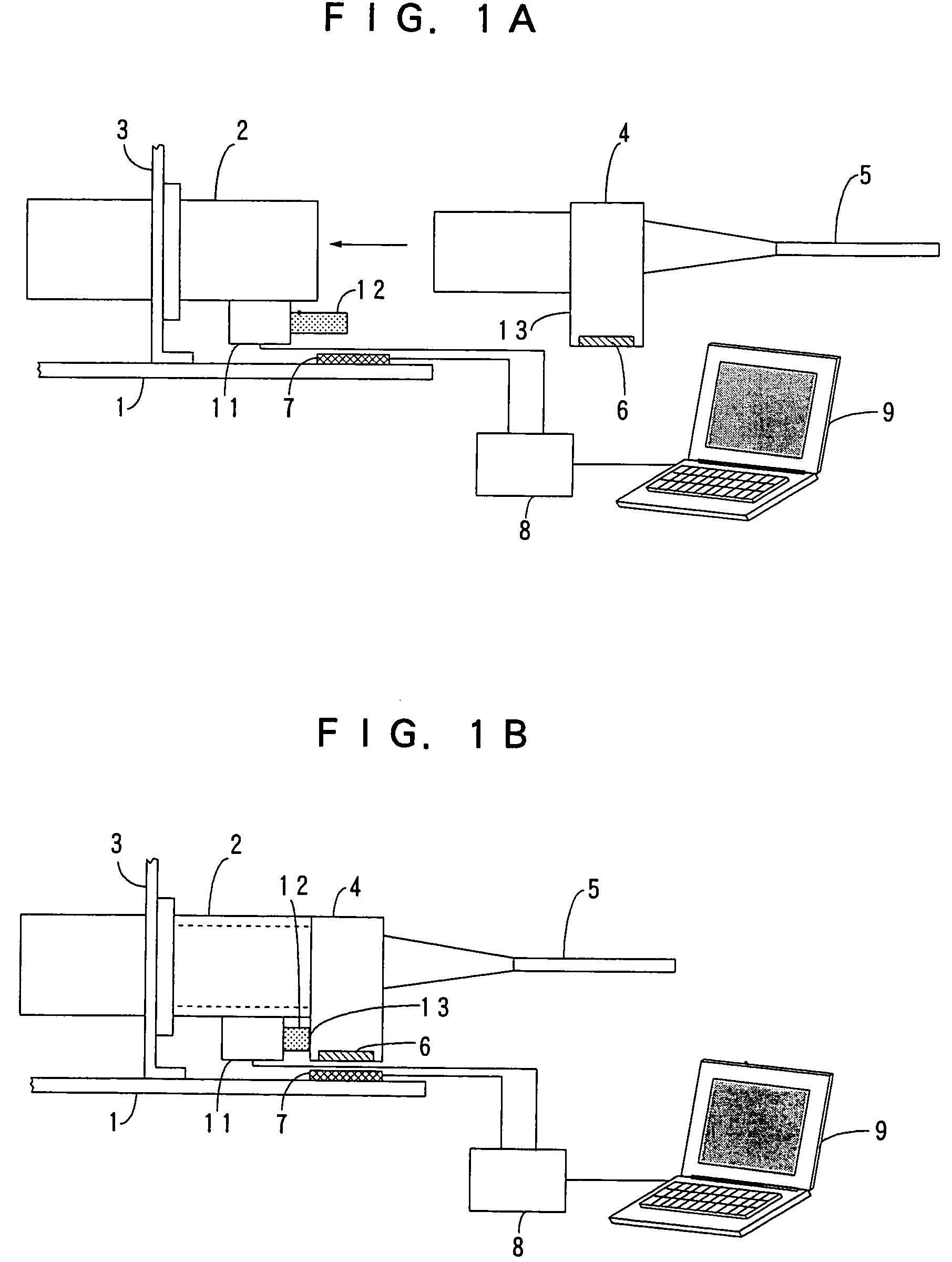
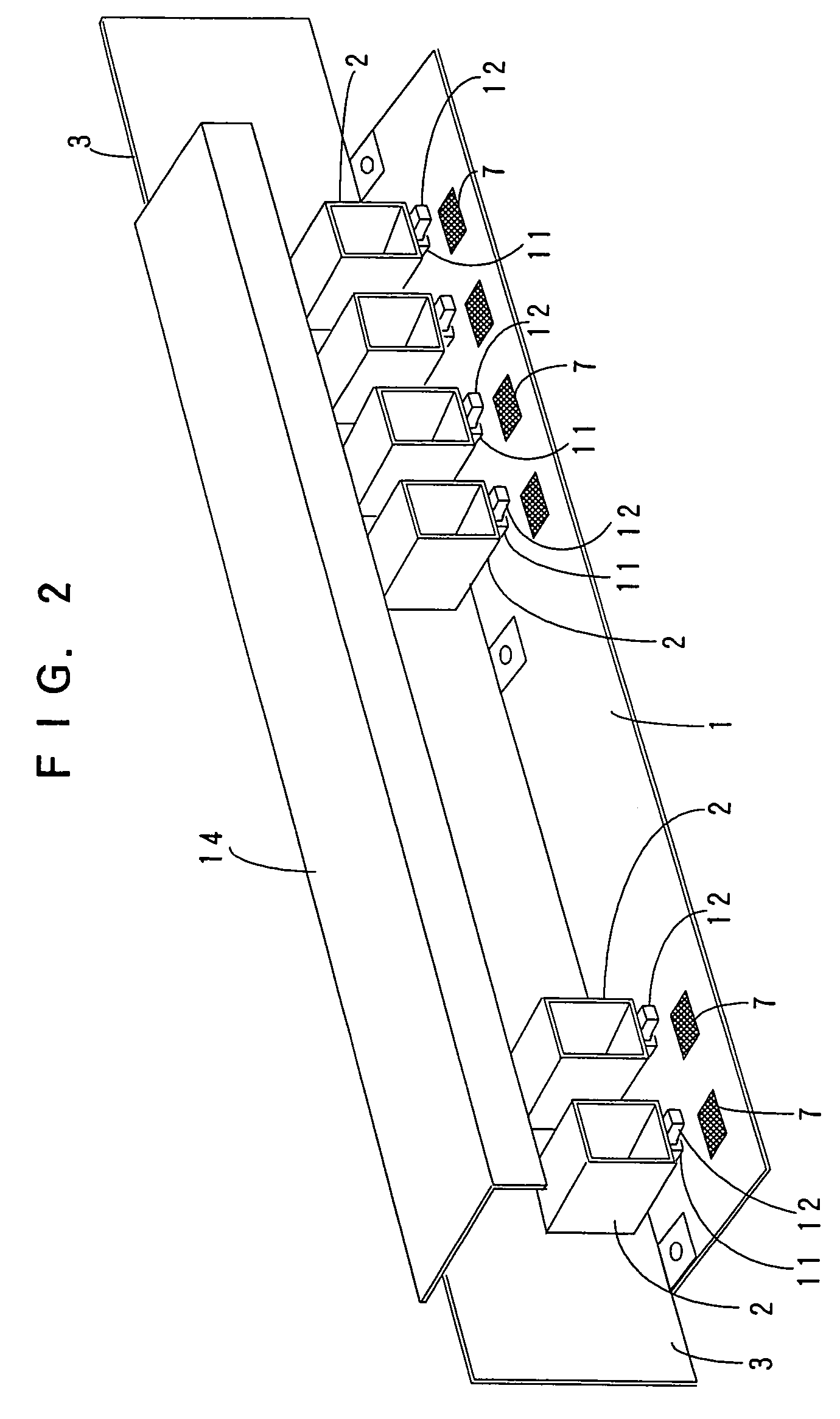
[0028]An example of a connector adapter of the present invention with memory function unit for control information will be described with reference to FIG. 1A and FIG. 1B. FIG. 1A illustrates a preceding state from a coupling state of the adapter to a plug, and FIG. 1B illustrates the wireless transmission coupling state of the adapter to a plug. In this example of the present invention, a non-lock detector switch 11 is provided at the lower side of the adapter 2 so as to be switched by a controlled bar 12 of the detector switch 11 when the connector plug 4 is coupled to the adapter 2. In this case, the detector switch 11 is exactly switched when the memory function unit 6 of the connector plug 4 reaches an upside of the antenna 7 provided on a supporting board 1.

[0029]When a plug of the connector 4 is connected with insertion coupling to the adapter 2, the detector switch 11 is switched to the ON-state, so that the unconnected state of the adapter 2 is changed to the connected stat...


PUM


Abstract

A non-lock detector switch is provided on or near an adapter to be switched by a connector plug when the connector plug with memory function unit is coupled to the adapter having an antenna for accessing to the memory function unit. Accordingly, connection state of each connector can be directly and simultaneously detected by the switching operation of the detector switch at a time preceding a little from a time when the antenna detects the memory function unit just having closed to a position opposed to the antenna. This is useful for exactly and detecting without delay the complete coupling state of each one of a number of adapters in distinction from the incomplete coupling state of any one of adapters.

Description

BACKGROUND OF INVENTION[0001]The present invention relates to a connector adapter with memory function unit for control information.[0002]On many conventional connectors, a label or a tape, on which optional letters or bar codes are recorded, is pasted for individual control information. In other examples, grouped control information, such as lot numbers or manufactured dates, is recorded.[0003]In case of controlling production steps or mounting and wiring steps of optical connectors in these conditions, such control operations are usually performed by the use of computers. In this case, mistake such as erroneous understanding or erroneous inputting of control information shall be occasionally occurred, if letters are employed as the control information, since an operator performs the inputting operations in reading of the letters of control information.[0004]On the other hand, in a case where the control information of bar code is recorded, read-in operations of control information...

Claims


Application Information

Patent Timeline
Patent Type & Authority Patents(United States)
IPC IPC(8): G02B6/36G02B6/38H01R13/641H01R13/66H01R13/70H01R13/703
CPCG02B6/3895H01R13/6683G02B6/3825H01R13/7038H01R2201/06Y10S439/916
Inventor SAGO, MASUYUKIENOMOTO, MASANORIIMAMURA, SUSUMUOOTAKA, YUKIEKOYAMA, DAISUKE
Owner TOKYO TSUSHINKI INDS
Learn More